Mouse Droid
Mouse Droid mouse-droid List D0001
This document shows a system architecture
and software architecture for the mouse droid MoD5G.
The MoD5G is a small repair droid similar to the MSE-6 used on death star 1.
The structure of the system architecture is loosely based on arc42.
The software architecture in chapter D0019 follows more exactly the arc42.org template
proposed by Gernot Starke and Peter Hruschka.
Copyright 2020-2026 Andreas Warnke
License:
Choose either Apache-2.0
or Creative Commons Attribution (BY) Licence
Mouse Droid
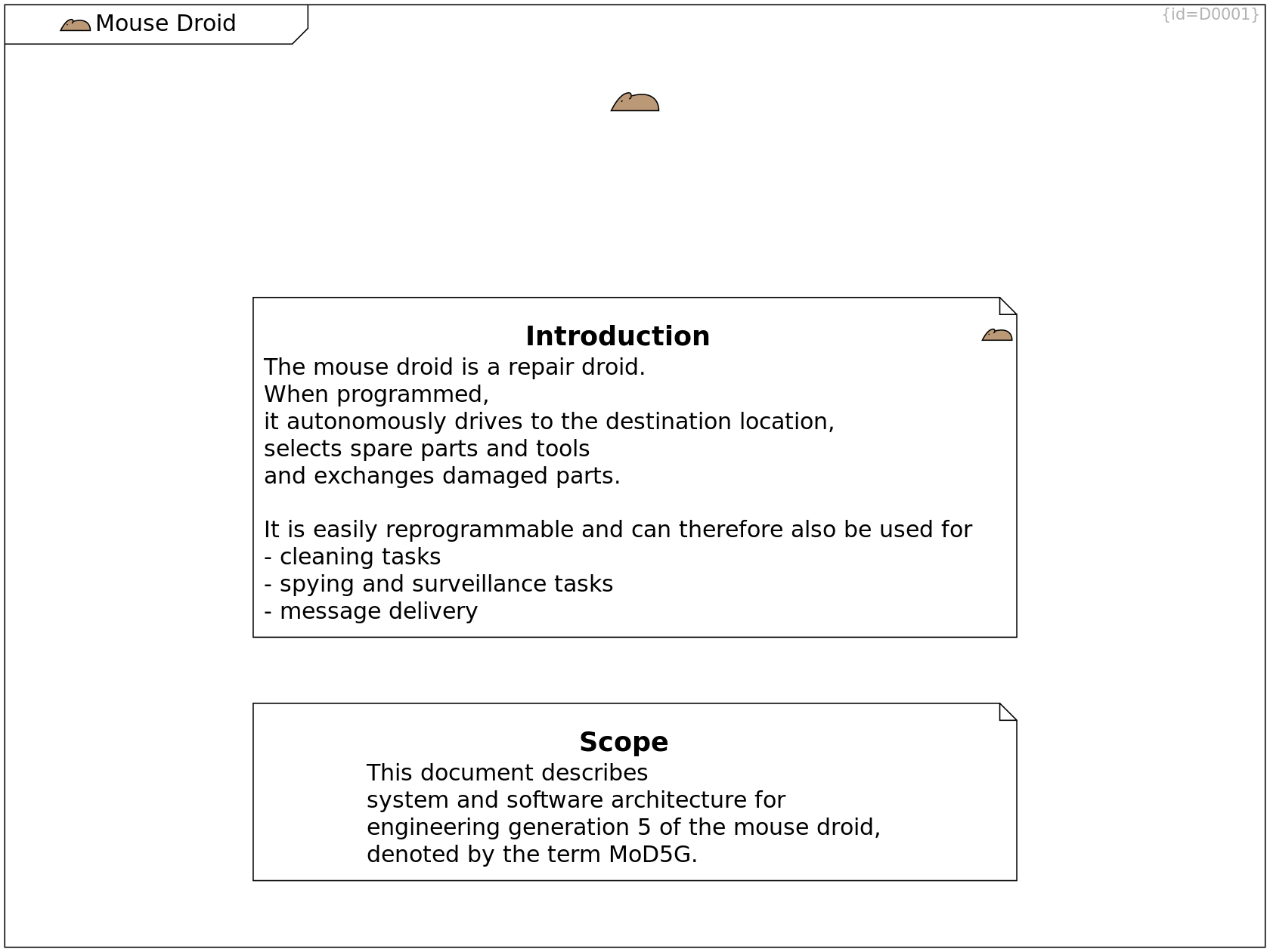
Scope of this Specification Comment C0141
This document describes system and software architecture
for engineering generation 5 of the mouse droid,
denoted by the term MoD5G.
Mouse Droid
MoD5G mouse-droid Image C0173
A brown mouse is the symbol for the MoD5G project.
Mouse Droid
Purpose of MoD5G Comment C0203
The main purpose of the MoD5G droid is
to repair mechanical, electrical and logical elements
at remote locations.
Goal
Goal Box Overview D0058
This section describes the goal of the MoD5G project. This is a short description of the functionality and a list of the main features.
The next sections then show Constraints and Scope and Context.
Goal
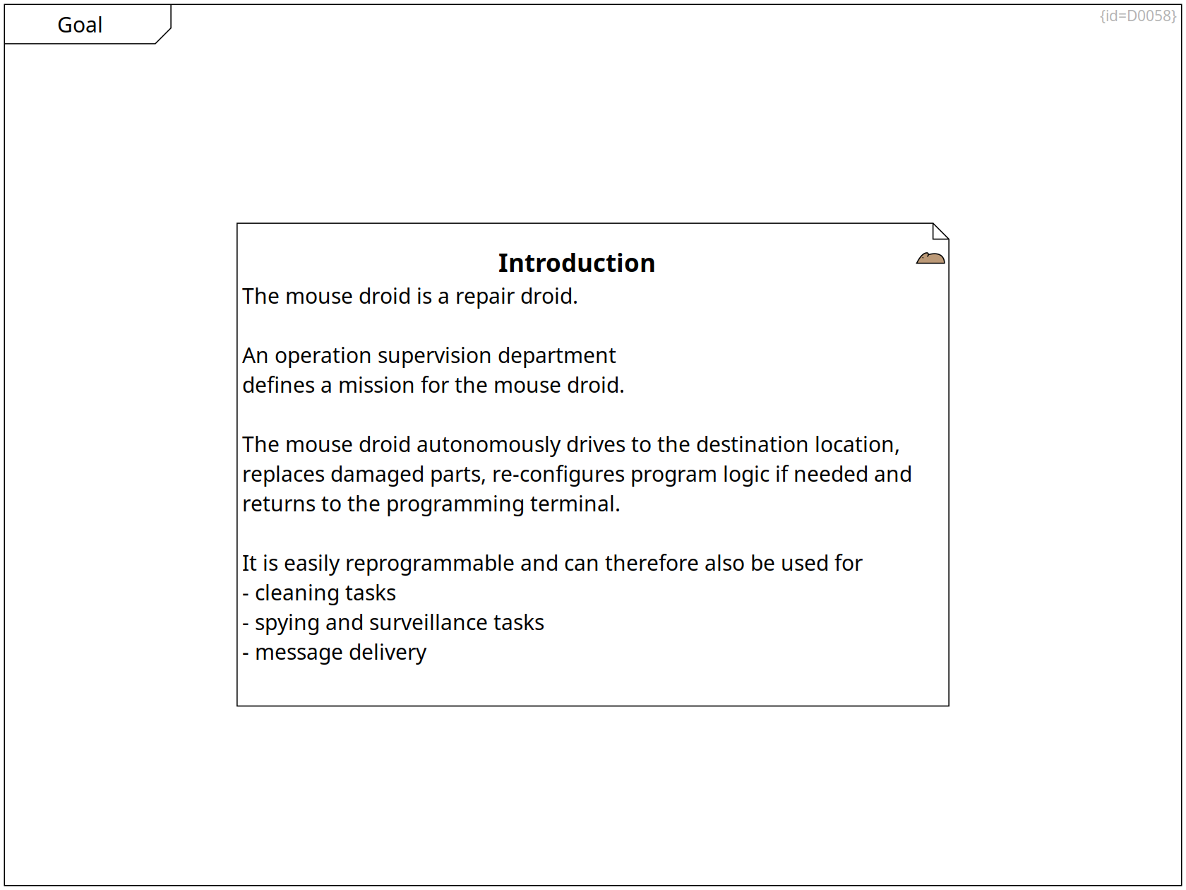
Introduction mouse-droid Comment C0001
The mouse droid is a repair droid.
An operation manager
defines a mission for the mouse droid.
The mouse droid autonomously drives to the destination location,
replaces damaged parts, re-configures program logic if needed and
returns to the programming terminal.
The mouse droid is easily reprogrammable
and can therefore also be used for
- cleaning tasks
- spying and surveillance tasks
- message delivery
High-level Features
High-level Features Requirement Diagram D0070
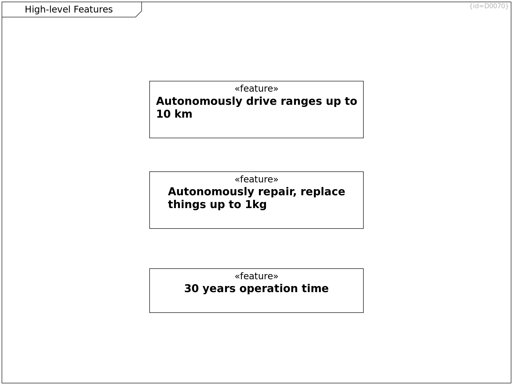
A list of high-level features is shown here.
Maintainability, High-level Features
30 years operation time feature Requirement C0223
The MoD5G shall be designed for a lifetime of 30 years.
Requirements on Moving, High-level Features
Autonomously drive ranges up to 10 km feature Requirement C0224
The MoD5G shall reach target locations and be able to return to its base station.
The range shall be 10 km or more.
High-level Features, Requirements on Tool Usage
Autonomously repair, replace things up to 1kg feature Requirement C0225
The MoD5G shall autonomously repair or clean things or gather intelligence.
Repairing includes replacing parts of up to 1kg weight.
Constraints
Constraints Requirement Diagram D0003
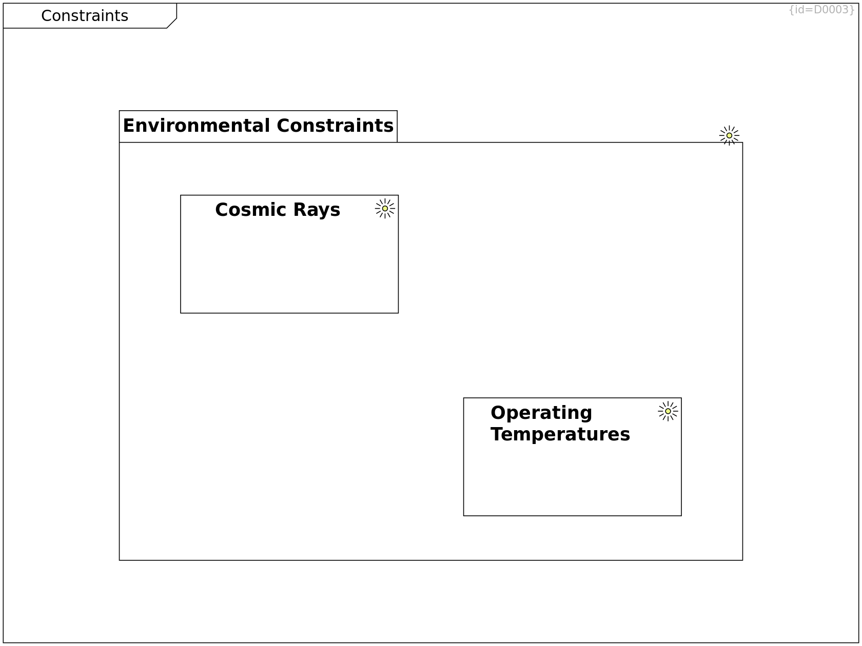
This section explains the major obstacles that need to be considered when designing a solution to Goal. (Problem Space, System Level)
Constraints
Operating Temperatures environment Requirement C0003
The droid shall be functional in the range 240K..360K,
it shall survive temperatures from 150K to 400K.
Constraints, Architecture Decisions
Cosmic Rays environment Requirement C0002
The droid shall ensure data and program integrity.
It shall continue operation after cosmic rays have interfered with data storage or program execution.
Corrupted data must not be stored permanently.
Constraints
Environmental Constraints environment Package C0144
This package lists technical/physical constraints imposed by the environment in which to operate.
+-- Cosmic Rays Containment R0221
+-- Operating Temperatures Containment R0222
Group of constratins imposed by the operation environment
Scope and Context
Scope and Context Block Definition Diagram D0066
This section shows
- the users
- the uses (intended, unintended, misuses)
- the external conditions
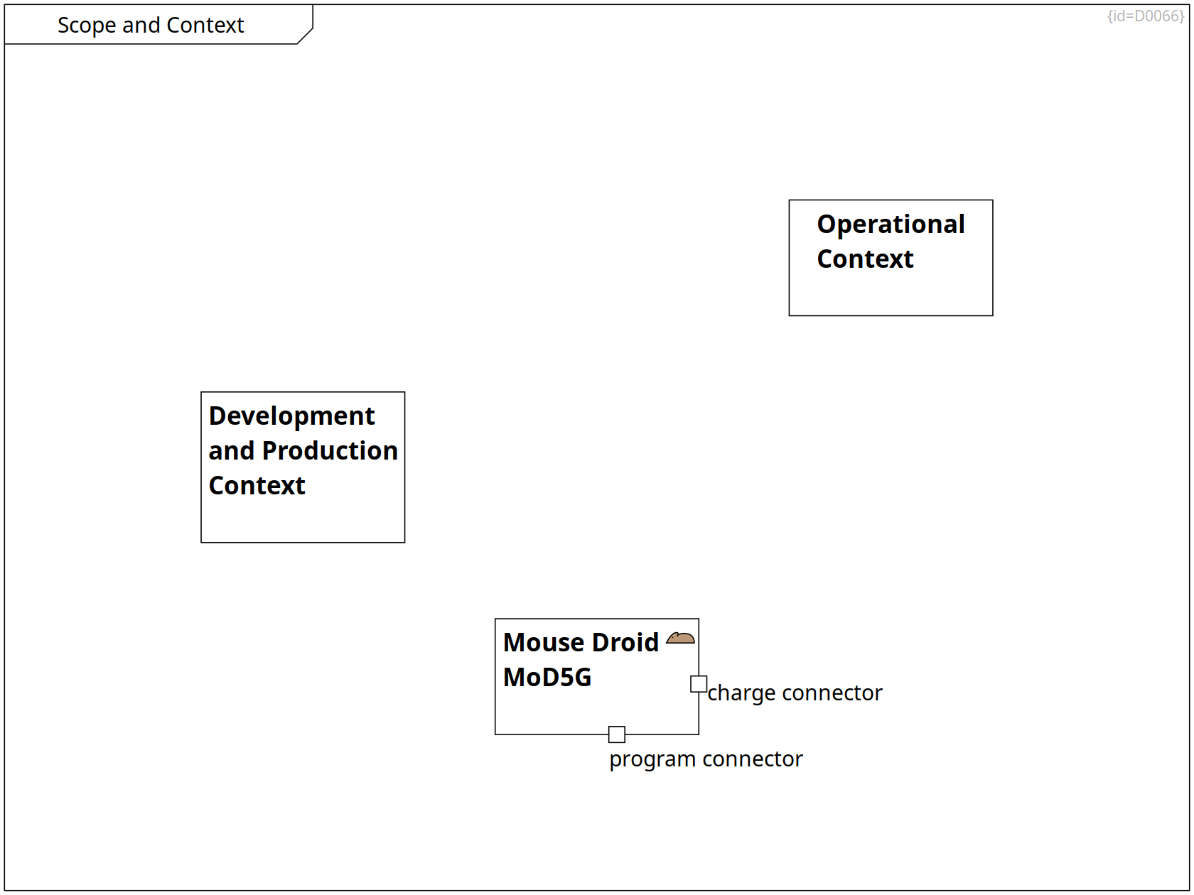
Scope and Context, Lifecycle, Operational Context
Operational Context Subsystem C0089
This boundary encompasses the topics that are in scope during operation and maintenance.
Scope and Context, Lifecycle, Factory Context
Development and Production Context Subsystem C0088
This boundary encompasses the topics that are in scope during development and production.
Scope and Context, Use Cases and Requirements, Factory Context, Requirements and Goals, Operational Context, Scope and Context, Deployment View
Mouse Droid MoD5G mouse-droid Subsystem C0004
The Mouse Droid (MoD5G) is a repair droid that can be instructed to perform a mission and which then autonomously selects tactics to achieve the mission goals.
charge connector Port F0074
Via the charge connector, the energy call can be refreshed.
program connector Port F0075
Via the program connector, an operator provides the data for a mission to be performed.
Lifecycle
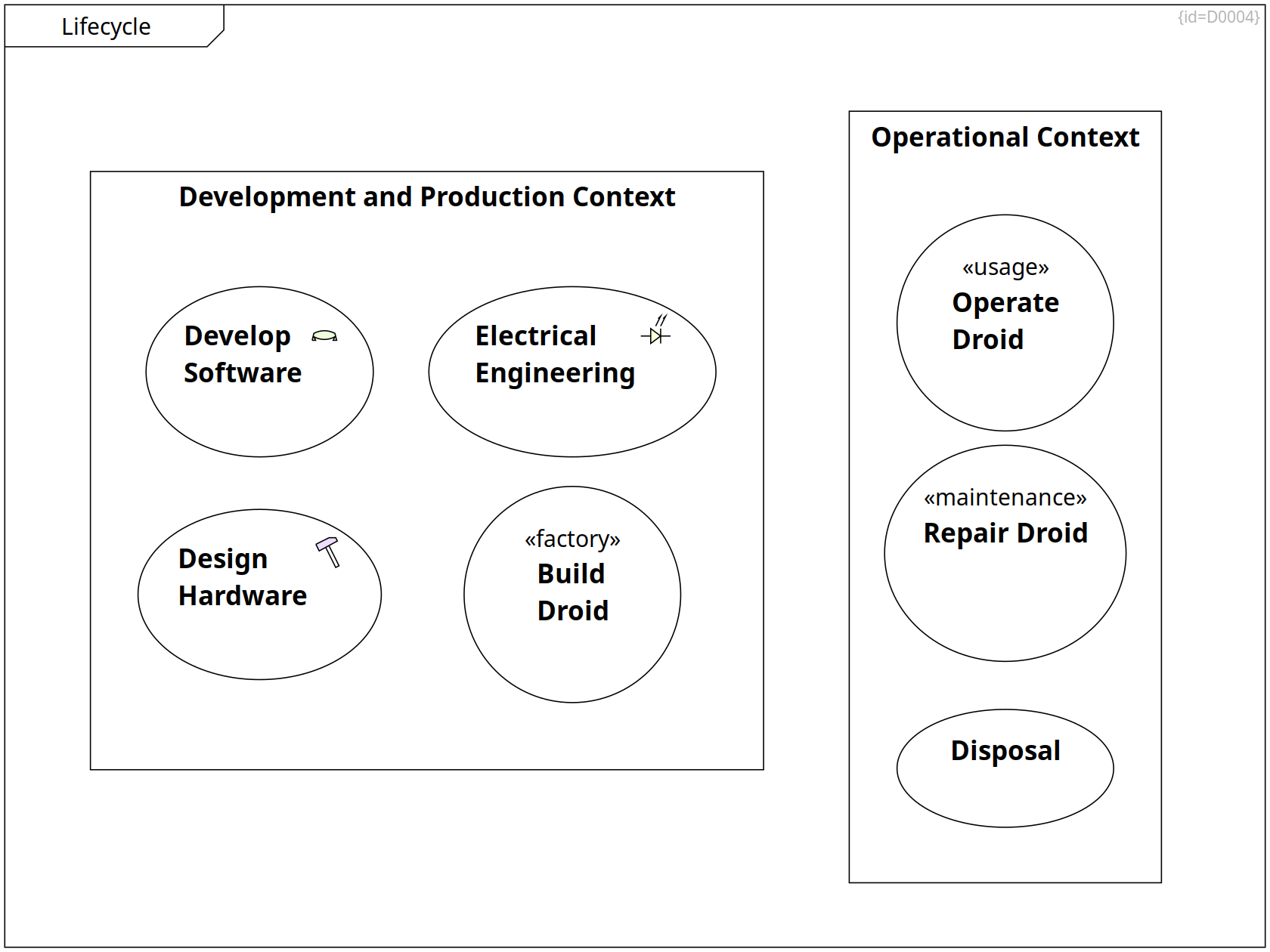
Lifecycle Use Case Diagram D0004
This diagram shows the contexts of development / production and operational environments. (Problem Space, System Level)
Scope and Context, Lifecycle, Factory Context
Development and Production Context Subsystem C0088
This boundary encompasses the topics that are in scope during development and production.
+-- Electrical Engineering Containment R0188
+-- Design Hardware Containment R0187
+-- Develop Software Containment R0125
+-- Build Droid Containment R0124
Scope and Context, Lifecycle, Operational Context
Operational Context Subsystem C0089
This boundary encompasses the topics that are in scope during operation and maintenance.
+-- Repair Droid Containment R0127
+-- Operate Droid Containment R0126
+-- Disposal Containment R0353
Lifecycle
Build Droid factory Use Case C0090
At the factory, workers assemble hardware and electronic parts to mouse droids and integrate control logic and data.
Lifecycle
Develop Software SW Use Case C0091
A team of engineers designs, produces and tests the control logic and factory data of the droids.
Lifecycle
Operate Droid usage Use Case C0092
An operator instructs the mouse droid which mission to perform.
The logic of the mouse droid translates this mission into driving maneuvers and actions of the integrated tools.
Lifecycle
Repair Droid maintenance Use Case C0093
A service mechanic analyzes the health state of a mouse droid.
Depending on the outcome, oil is refilled, logic is updated, parts are exchanged or the whole droid is disintegrated.
Lifecycle
Design Hardware HW Use Case C0135
A team of engineers designs, produces and tests the mechanical hardware parts of the droids.
Lifecycle
Electrical Engineering EE Use Case C0136
A team of engineers designs, produces and tests the electrical and electronic parts of the droids.
Lifecycle
Disposal Use Case C0210
The interstellar space is a good location for damaged droids (see flow in Health States).
Factory Context
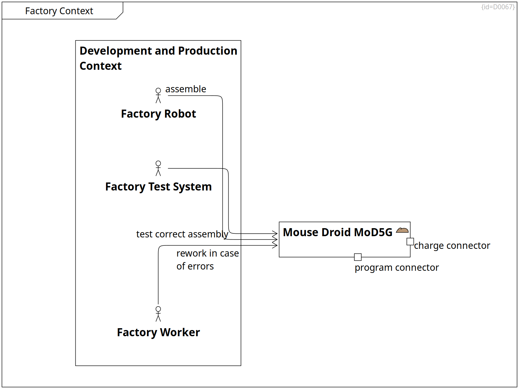
Factory Context Component Diagram D0067
This diagram shows the actors in the production environment. (Problem Space, System Level)
Scope and Context, Lifecycle, Factory Context
Development and Production Context Subsystem C0088
This boundary encompasses the topics that are in scope during development and production.
+-- Factory Worker Containment R0364
+-- Factory Robot Containment R0365
+-- Factory Test System Containment R0366
Factory Context
Factory Robot Actor C0212
assemble --> Mouse Droid MoD5G Association R0368
A robot assembles HW and EE parts.
It integrates the program logic and configures the MoD5G.
Factory Context
Factory Worker Actor C0211
rework in case of errors --> Mouse Droid MoD5G Association R0367
Factory Context
Factory Test System Actor C0213
test correct assembly --> Mouse Droid MoD5G Association R0369
A test system
- checks that parts are working
- checks communication between the parts
Scope and Context, Use Cases and Requirements, Factory Context, Requirements and Goals, Operational Context, Scope and Context, Deployment View
Mouse Droid MoD5G mouse-droid Subsystem C0004
The Mouse Droid (MoD5G) is a repair droid that can be instructed to perform a mission and which then autonomously selects tactics to achieve the mission goals.
charge connector Port F0074
Via the charge connector, the energy call can be refreshed.
program connector Port F0075
Via the program connector, an operator provides the data for a mission to be performed.
Operational Context
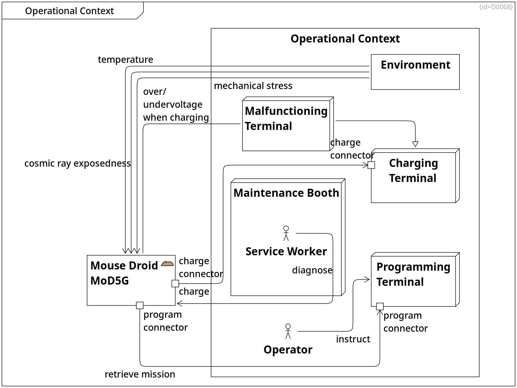
Operational Context Component Diagram D0068
This diagram shows the actors in the operational context. (Problem Space, System Level)
Scope and Context, Use Cases and Requirements, Factory Context, Requirements and Goals, Operational Context, Scope and Context, Deployment View
Mouse Droid MoD5G mouse-droid Subsystem C0004
The Mouse Droid (MoD5G) is a repair droid that can be instructed to perform a mission and which then autonomously selects tactics to achieve the mission goals.
charge connector Port F0074
Via the charge connector, the energy call can be refreshed.
program connector Port F0075
Via the program connector, an operator provides the data for a mission to be performed.
retrieve mission --> Programming Terminal Association R0378
The MoD5G connects to a terminal in order to retrieve the next mission to be performed.
charge --> Charging Terminal Association R0379
The MoD5G connects to a terminal in order to charge its energy cell.
Scope and Context, Lifecycle, Operational Context
Operational Context Subsystem C0089
This boundary encompasses the topics that are in scope during operation and maintenance.
+-- Environment Containment R0370
+-- Malfunctioning Terminal Containment R0381
+-- Operator Containment R0384
+-- Service Worker Containment R0385
+-- Charging Terminal Containment R0374
+-- Programming Terminal Containment R0375
+-- Maintenance Booth Containment R0376
Operational Context
Environment Subsystem C0214
cosmic ray exposedness --> Mouse Droid MoD5G Association R0371
In thin atmospheres, cosmic rays are not completely absorbed and may interfere with the program logic and with stored data on the MoD5G.
mechanical stress --> Mouse Droid MoD5G Association R0372
The MoD5G has to cope with constant vibrations while moving, but also with sudden strokes.
temperature --> Mouse Droid MoD5G Association R0373
The MoD5G has to cope with extreme high and low temperatures.
Operational Context, Deployment View
Charging Terminal Node C0097
This terminal charges the energy cell of the MoD5G.
charge connector Port F0072
Via the charge connector, the energy call of the MoD5G or other droids can be refreshed.
Operational Context, Deployment View
Programming Terminal Node C0096
This terminal programs the next mission for the MoD5G.
program connector Port F0073
Via the program connector, an operator instructs the MoD5G on the mission to be performed.
Operational Context, Deployment View
Maintenance Booth Node C0098
At this booth, a mechanic analyzes the health of the MoD5G and replaces parts if damaged.
+-- Service Worker Containment R0386
Operational Context
Malfunctioning Terminal Node C0215
--|> Charging Terminal Generalization R0382
over/undervoltage when charging -- Mouse Droid MoD5G Communication Path R0383
In case a terminal provides an unsuitable charging voltage, the MoD5G shall stop the charging attempt.
Use Cases and Requirements, Operational Context, Scope and Context
Operator Actor C0216
instruct --> Programming Terminal Association R0387
Operational Context
Service Worker Actor C0217
diagnose --> Mouse Droid MoD5G Association R0390
A service mechanic analyses the MoD5G for health state and damages.
Use Cases and Requirements
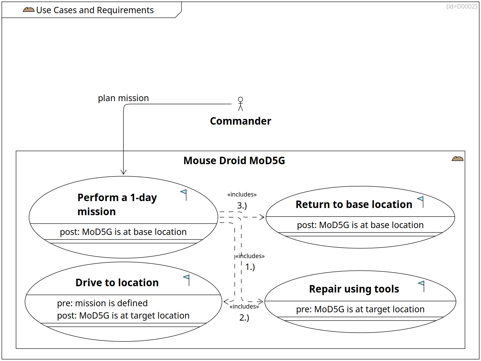
Use Cases and Requirements mouse-droid Use Case Diagram D0002
This section gives a short overview on the project goals (Problem Space, System Level)
Primary purpose of the MoD5G is to autonomously repair mechanical things.
Scope and Context, Use Cases and Requirements, Factory Context, Requirements and Goals, Operational Context, Scope and Context, Deployment View
Mouse Droid MoD5G mouse-droid Subsystem C0004
The Mouse Droid (MoD5G) is a repair droid that can be instructed to perform a mission and which then autonomously selects tactics to achieve the mission goals.
charge connector Port F0074
Via the charge connector, the energy call can be refreshed.
program connector Port F0075
Via the program connector, an operator provides the data for a mission to be performed.
+-- Perform a 1-day mission Containment R0001
+-- Return to base location Containment R0283
+-- Drive to location Containment R0003
+-- Repair using tools Containment R0004
Use Cases and Requirements
Perform a 1-day mission goal Use Case C0006
The mouse droid is able to perform a mission that takes several hours. The energy resources of the MoD5G last for one terrestrial day.
- The operator programs a mission
- The mouse droid drives to the first location
- The mouse droid uses tools to remove a defective part
- The mouse droid installs a spare part
- Above steps are repeated for further mission objectives
- The mouse droid returns to its base location (see Glossary)
post: MoD5G is at base location Property F0034
1.) move ··> Drive to location Inclusion R0005
2.) repair ··> Repair using tools Inclusion R0006
3.) return ··> Return to base location Inclusion R0284
Use Cases and Requirements, Requirements and Goals, Requirements on Moving, Functionality per Mode
Drive to location goal Use Case C0007
The mouse droid can explore its environment and calculate a route from its actual position to the target location.
- The mouse droid explores its environment
- The mouse droid enriches an internally memorized map
- The mouse droid calculates a route
- The mouse droid drives along the calculated route
- The mouse droid re-caclulates the route in case of new environment data
- The mouse droid reaches the target location
pre: mission is defined Property F0032
post: MoD5G is at target location Property F0043
Use Cases and Requirements, Requirements and Goals, Requirements on Tool Usage, Functionality per Mode
Repair using tools goal Use Case C0008
The mouse droid has a couple of tools inside its chassis.
- The mouse droid uses a screw diver to untighten damaged parts
- The mouse droid uses a gripper to move the damaged part out of the way
- The mouse droid uses a gripper to put a spare part from its internal cargo bin to the target place
- The mouse droid uses a screw diver to tighten replaced parts
- The mouse droid uses a gripper to move the damaged part into its internal cargo bin.
(see Mechanics)
pre: MoD5G is at target location Property F0044
Use Cases and Requirements, Requirements on Moving, Functionality per Mode
Return to base location goal Use Case C0177
The MoD5G returns to its base location.
Note: Base location is defined at Glossary.
post: MoD5G is at base location Property F0033
Use Cases and Requirements, Operational Context, Scope and Context
Operator Actor C0216
plan mission --> Perform a 1-day mission Association R0391
Requirements on Moving
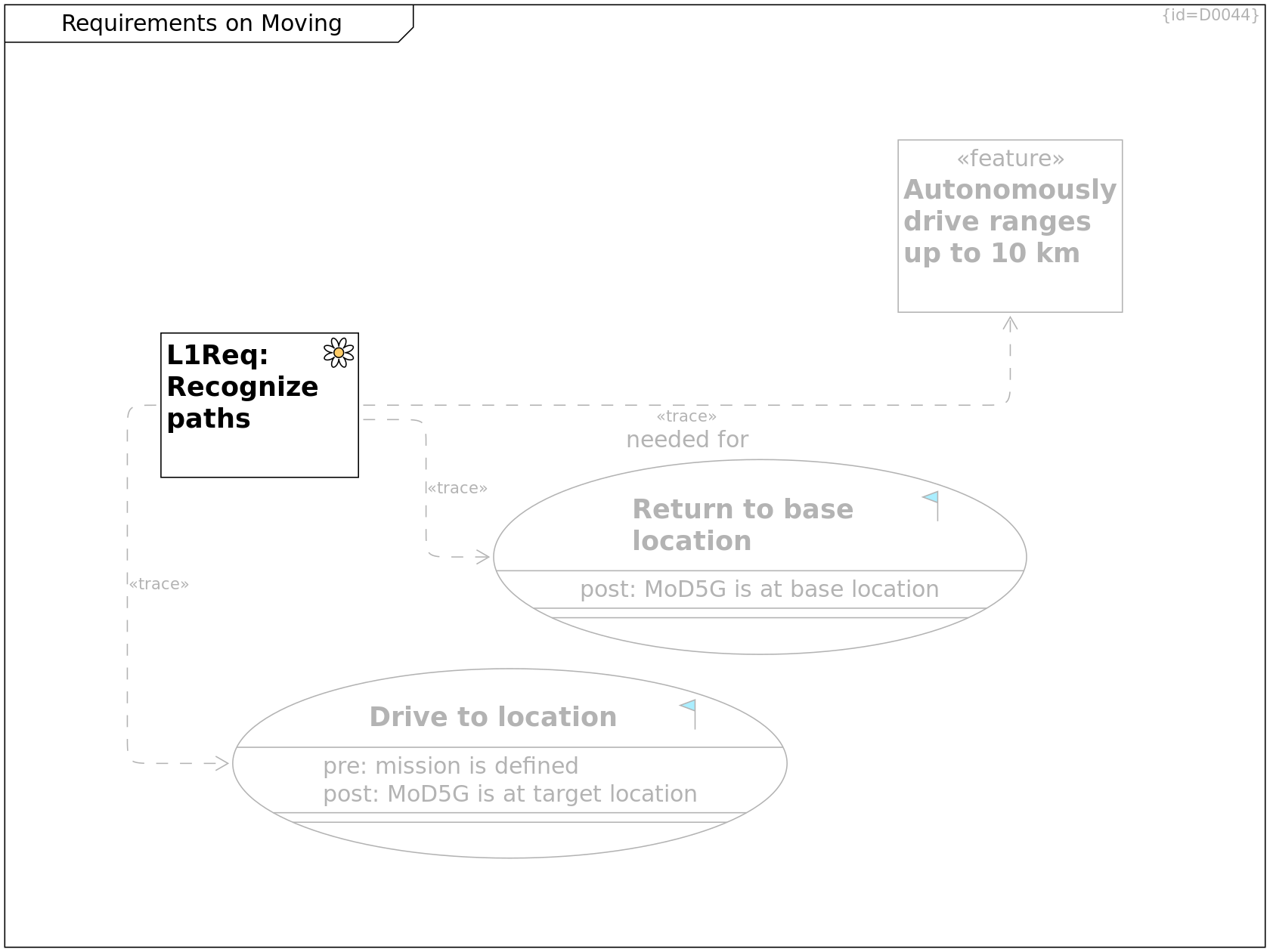
Requirements on Moving Requirement Diagram D0044
This diagram shows the system level requirements related to driving use cases.
Use Cases and Requirements, Requirements and Goals, Requirements on Moving, Functionality per Mode
Drive to location goal Use Case C0007
The mouse droid can explore its environment and calculate a route from its actual position to the target location.
- The mouse droid explores its environment
- The mouse droid enriches an internally memorized map
- The mouse droid calculates a route
- The mouse droid drives along the calculated route
- The mouse droid re-caclulates the route in case of new environment data
- The mouse droid reaches the target location
pre: mission is defined Property F0032
post: MoD5G is at target location Property F0043
Requirements on Moving, Requirements, Functions covering Requirements
SYS-Req: Recognize paths env-perception Requirement C0149
The MoDG5 shall use redundant sensor data to calculate paths that it can drive along.
··> Drive to location Trace R0244
··> Return to base location Trace R0285
needed for ··> Autonomously drive ranges up to 10 km Trace R0402
Use Cases and Requirements, Requirements on Moving, Functionality per Mode
Return to base location goal Use Case C0177
The MoD5G returns to its base location.
Note: Base location is defined at Glossary.
post: MoD5G is at base location Property F0033
Requirements on Moving, High-level Features
Autonomously drive ranges up to 10 km feature Requirement C0224
The MoD5G shall reach target locations and be able to return to its base station.
The range shall be 10 km or more.
Requirements on Tool Usage
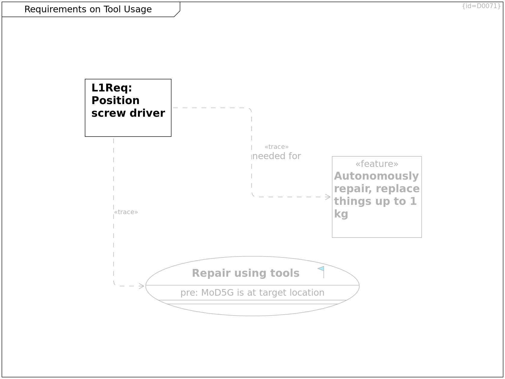
Requirements on Tool Usage Requirement Diagram D0071
This diagram shows the system level requirements related to repairing use cases.
Requirements, Functions covering Requirements, Requirements on Tool Usage
SYS-Req: Position screw driver Requirement C0150
The MoDG5 shall bring the screw driver into a given 3D position.
··> Repair using tools Trace R0245
needed for ··> Autonomously repair, replace things up to 1kg Trace R0403
High-level Features, Requirements on Tool Usage
Autonomously repair, replace things up to 1kg feature Requirement C0225
The MoD5G shall autonomously repair or clean things or gather intelligence.
Repairing includes replacing parts of up to 1kg weight.
Use Cases and Requirements, Requirements and Goals, Requirements on Tool Usage, Functionality per Mode
Repair using tools goal Use Case C0008
The mouse droid has a couple of tools inside its chassis.
- The mouse droid uses a screw diver to untighten damaged parts
- The mouse droid uses a gripper to move the damaged part out of the way
- The mouse droid uses a gripper to put a spare part from its internal cargo bin to the target place
- The mouse droid uses a screw diver to tighten replaced parts
- The mouse droid uses a gripper to move the damaged part into its internal cargo bin.
(see Mechanics)
pre: MoD5G is at target location Property F0044
Quality Requirements
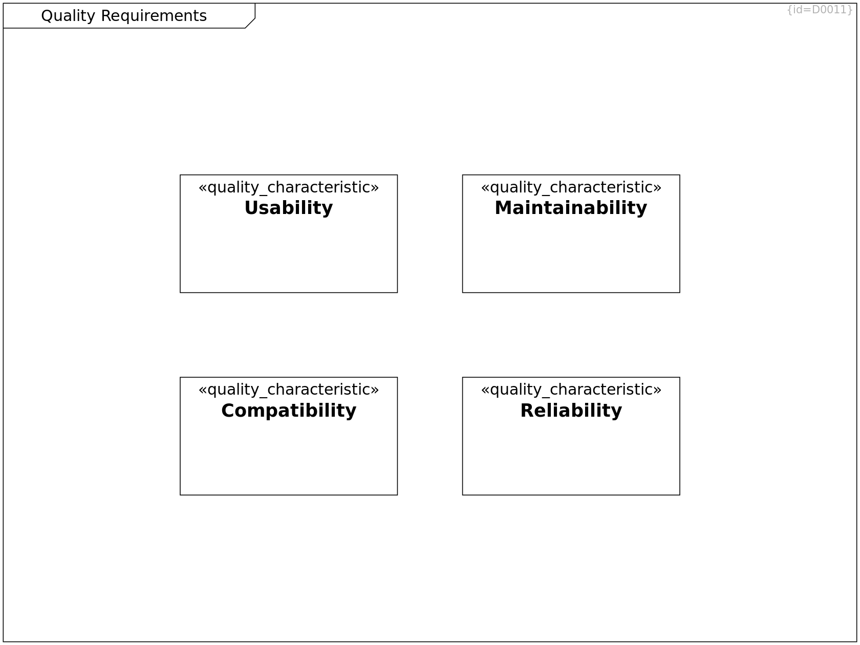
Quality Requirements Component Diagram D0011
This section shows the major quality requrements and scenarios. (Problem Space, System Level)
In the following, requirements and scenarios are presented that show the quality expectations: They focus on WHAT shall be implemented, not on the HOW.
Quality Requirements
Usability quality_characteristic Requirement C0009
Usability defines a set of attributes that measures how easy to learn and use the program is.
Maintainability, Quality Tree, Quality Requirements
Maintainability quality_characteristic Requirement C0010
Maintainability defines a set of attributes that influence how to analyze and mitigate defects that occur during operation.
Quality Requirements
Reliability quality_characteristic Requirement C0011
Reliability defines a set of attributes that measures how mature and fault-tolerant the software is.
Quality Tree, Quality Requirements, Quality Requirements
Compatibility quality_characteristic Requirement C0122
Compatibility defines a set of attributes that measures how well data and messages can be exchanged with other programs and/or versions.
Quality Tree
Quality Tree Requirement Diagram D0039
This section shows the quality requirements ordered by quality characteristics.
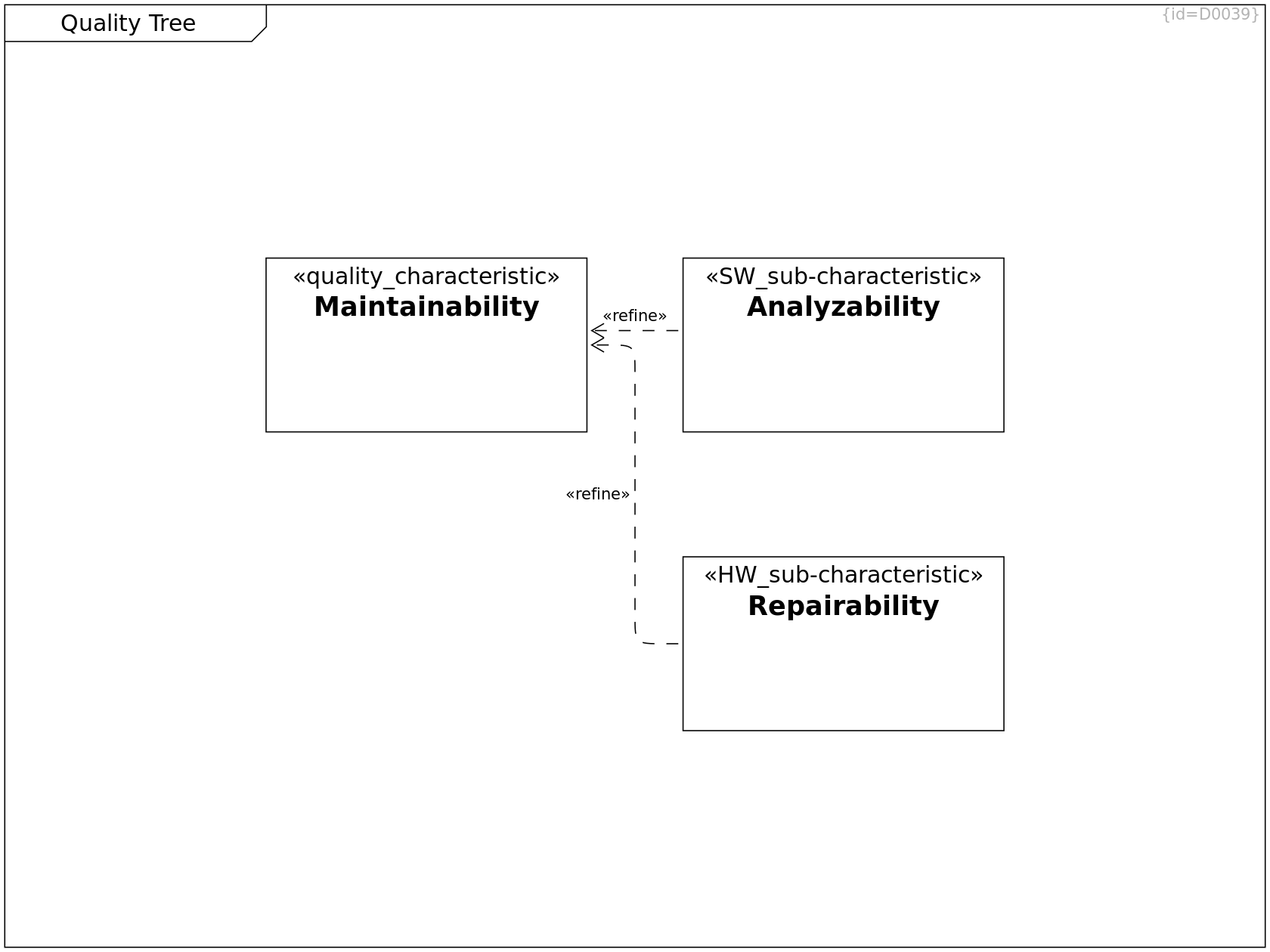
Maintainability, Quality Tree, Quality Requirements
Maintainability quality_characteristic Requirement C0010
Maintainability defines a set of attributes that influence how to analyze and mitigate defects that occur during operation.
Maintainability, Quality Tree, Quality Scenarios
Analyzability SW_sub-characteristic Requirement C0014
The MoD5G shall allow to analyze faults
that occurred during operation.
··> Maintainability Refinement R0009
Maintainability, Quality Tree, Quality Scenarios
Repairability HW_sub-characteristic Requirement C0012
The MoD5 hardware parts shall be exchangeable
in case they are damaged.
··> Maintainability Refinement R0007
Maintainability
Maintainability Requirement Diagram D0015
This diagram shows the quality requirements related to the characteristic "Maintainability".
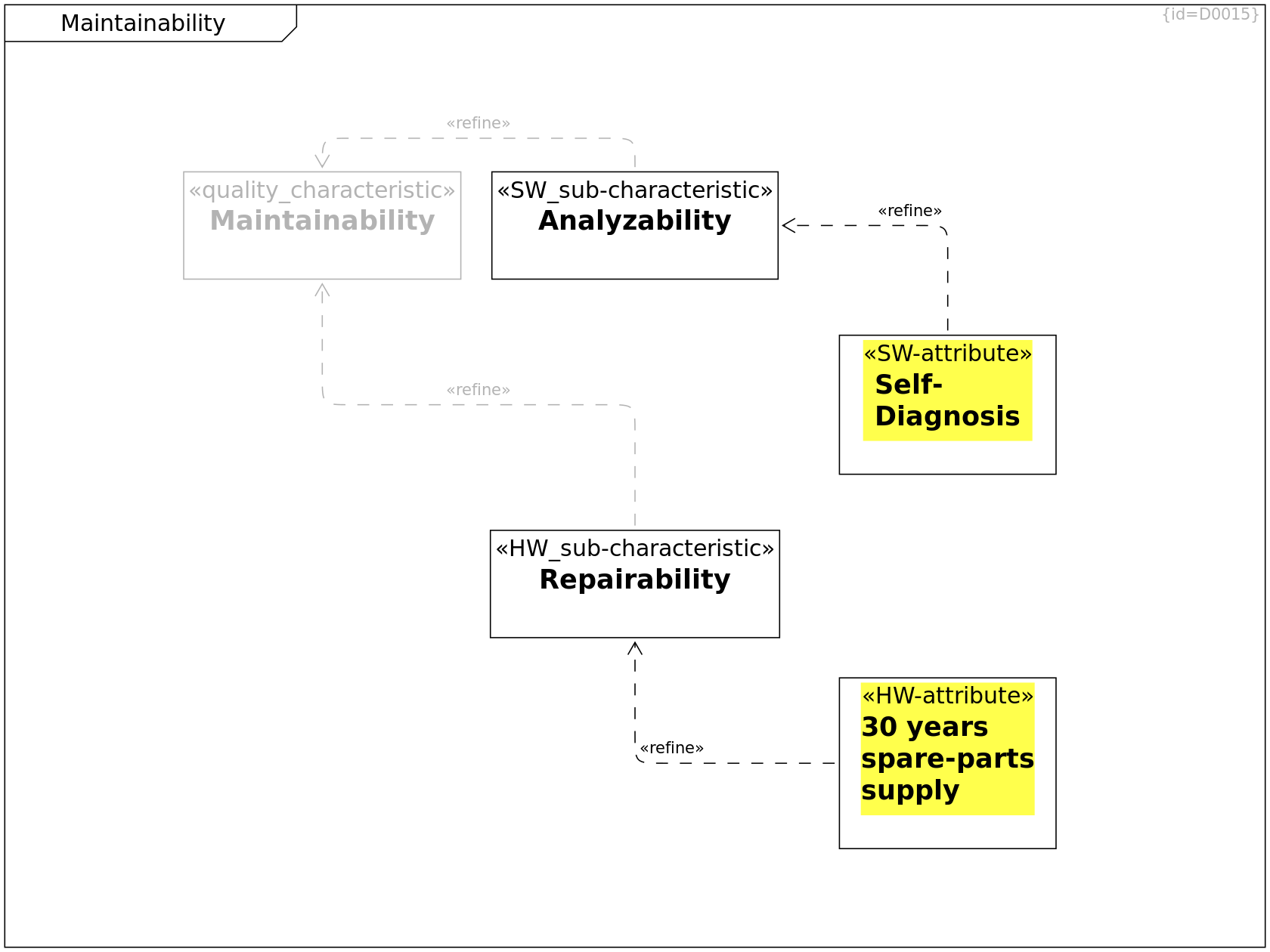
Maintainability, Quality Tree, Quality Requirements
Maintainability quality_characteristic Requirement C0010
Maintainability defines a set of attributes that influence how to analyze and mitigate defects that occur during operation.
Maintainability, Quality Tree, Quality Scenarios
Repairability HW_sub-characteristic Requirement C0012
The MoD5 hardware parts shall be exchangeable
in case they are damaged.
··> Maintainability Refinement R0007
Maintainability
30 years spare-parts supply HW-attribute Requirement C0013
The mechanical and electrical/electronics parts of the MoD5
shall be produceable in identical or similar form
and quality for 30 years after production of the unit.
··> Repairability Refinement R0008
needed for ··> 30 years operation time Trace R0401
Maintainability, Quality Tree, Quality Scenarios
Analyzability SW_sub-characteristic Requirement C0014
The MoD5G shall allow to analyze faults
that occurred during operation.
··> Maintainability Refinement R0009
Maintainability
Self-Diagnosis SW-attribute Requirement C0015
At the maintenance booth,
the MoD5G shall provide an error log.
This error log contains detected errors from operation
and related environment conditions.
It also lists possible causes(faults).
··> Analyzability Refinement R0010
needed for ··> 30 years operation time Trace R0404
Maintainability, High-level Features
30 years operation time feature Requirement C0223
The MoD5G shall be designed for a lifetime of 30 years.
Quality Scenarios
Quality Scenarios Use Case Diagram D0040
This section shows the quality-related scenarios in which the quality requirements shown in Quality Tree are of special importance.
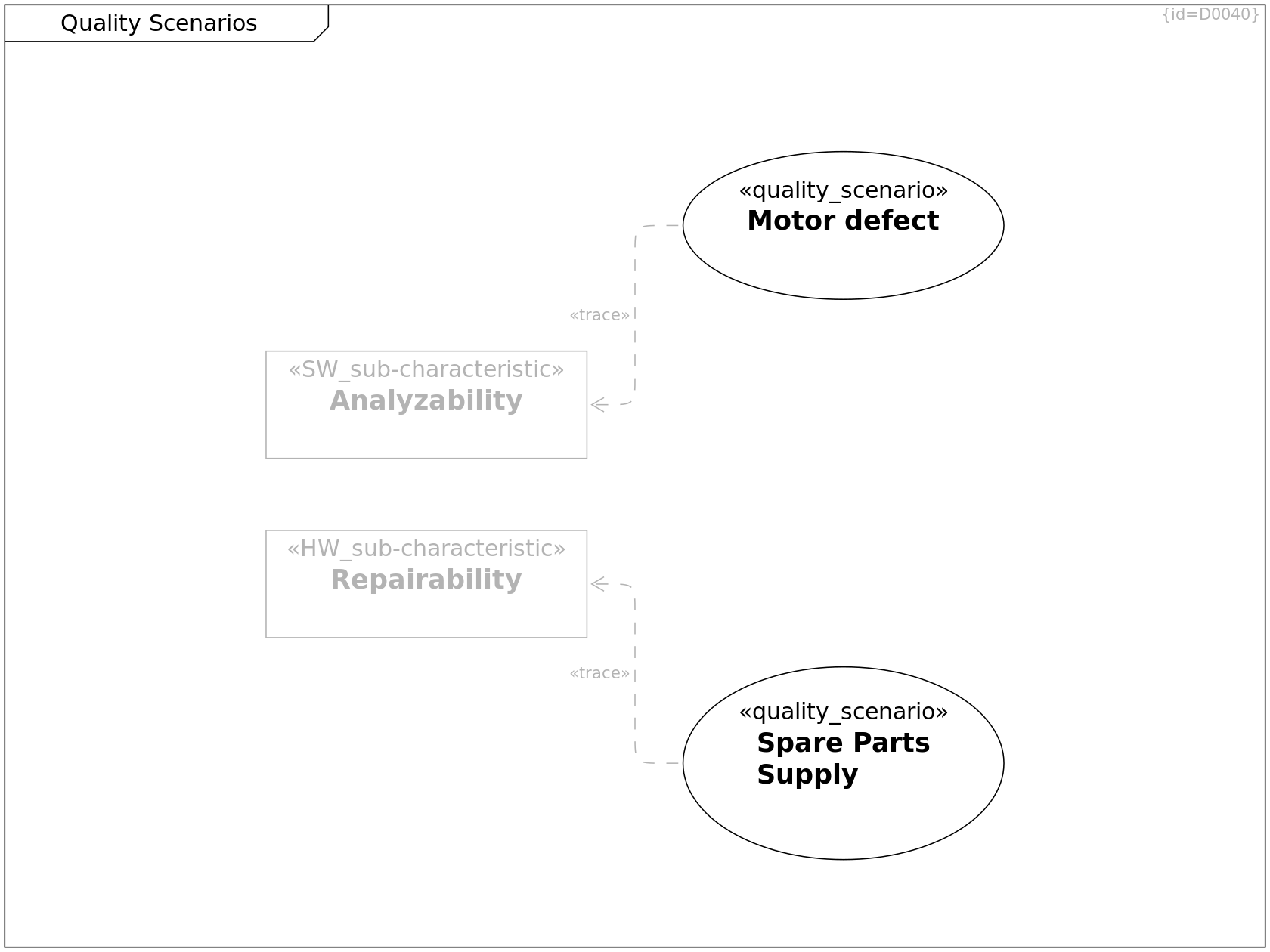
Quality Scenarios
Spare Parts Supply quality_scenario Use Case C0017
pre-condition:
- the stock of MoD5G spare parts is empty
trigger:
- 20 years after production,
a MoD5G needs a spare part that is not available anymore
scenario:
- a service mechanic orders a batch of parts
- a factory creates the parts that fit in form, function and quality to the MoD5G
- spare parts are delivered
··> Repairability Trace R0012
Quality Scenarios
Motor defect quality_scenario Use Case C0016
pre-condition:
- the MoD5G is performing a 1-day mission autonomously
trigger:
- a motor fails to operate
- the goals of the 1-day mission cannot be accomplished anymore
scenario:
- the MoD5G cancels the mission and returns to the service point
- a service mechanic reads out the error log
- the MoD5G proposes to replace the suspicious motor
- the service mechanic replaces the motor
··> Analyzability Trace R0197
Maintainability, Quality Tree, Quality Scenarios
Repairability HW_sub-characteristic Requirement C0012
The MoD5 hardware parts shall be exchangeable
in case they are damaged.
Maintainability, Quality Tree, Quality Scenarios
Analyzability SW_sub-characteristic Requirement C0014
The MoD5G shall allow to analyze faults
that occurred during operation.
Operation Modes
Operation Modes State Diagram D0053
Operation modes list all modes of the system that provide an intended subset of functionality.
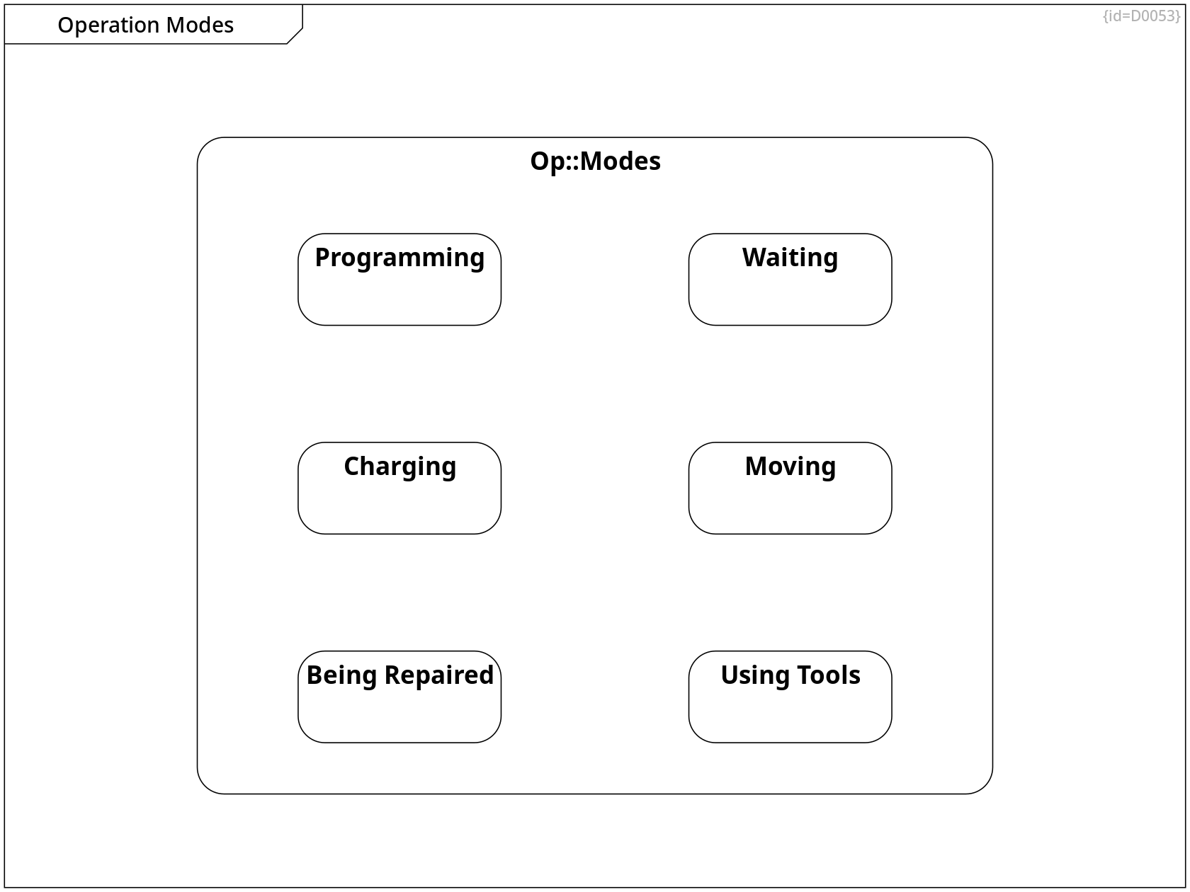
Operation Modes
Op::Modes State C0188
The operation modes list all modes in which different, intended subsets of functionality are available.
+-- Programming Containment R0299
+-- Using Tools Containment R0301
+-- Waiting Containment R0302
+-- Charging Containment R0298
+-- Moving Containment R0300
+-- Being Repaired Containment R0305
all tasks finished --> Waiting Control Flow R0315
Precondition:
- The Mod5G is at base location
- all tasks are finished
damaged --> Being Repaired Control Flow R0316
Precondition:
- The Mod5G is at maintenance booth
- The Mod5G is damaged
not fully charged --> Charging Control Flow R0317
Precondition:
- The Mod5G is at base location
- The Mod5G is not yet fully charged
operator starts programming --> Programming Control Flow R0318
Precondition:
- The Mod5G is at base location
- The operator starts programming
mission not completed --> Moving Control Flow R0319
Precondition:
- The Mod5G has not yet completed the mission
- The Mod5G is not at target location
tasks not completed --> Using Tools Control Flow R0320
Precondition:
- The Mod5G has its tasks not yet completed
- The Mod5G is at target location
Operation Modes
Charging State C0189
The charging mode allows to perform charging the batteries.
Operation Modes
Programming State C0190
The Programming mode allows an operator to program a mission.
Operation Modes, Functionality per movement-related mode, Functionality per Mode
Moving State C0191
The moving mode allows to move the MoD5G.
Operation Modes, Functionality per tool-related mode, Functionality per Mode
Using Tools State C0192
The using tools mode allows to repair or clean an object at the target location of the programmed mission.
Operation Modes, Functionality per movement-related mode, Functionality per tool-related mode, Functionality per Mode
Waiting State C0193
The waiting mode allows to perform nothing till an outside trigger changes the mode.
Operation Modes
Being Repaired State C0195
The being repaired mode allows an mechanic to read out log data and to replace hardware parts.
Functionality per Mode
Functionality per Mode Block Definition Diagram D0065
This diagram shows the intended subset of functionality for some operation modes.
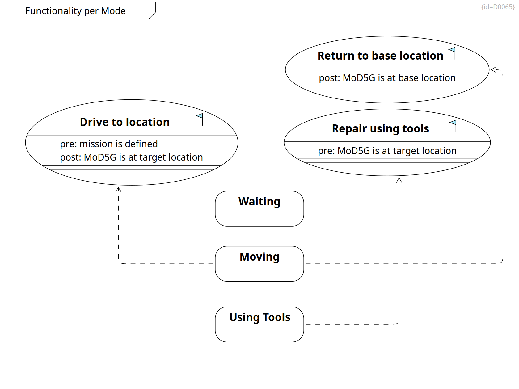
Use Cases and Requirements, Requirements on Moving, Functionality per Mode
Return to base location goal Use Case C0177
The MoD5G returns to its base location.
Note: Base location is defined at Glossary.
post: MoD5G is at base location Property F0033
Use Cases and Requirements, Requirements and Goals, Requirements on Tool Usage, Functionality per Mode
Repair using tools goal Use Case C0008
The mouse droid has a couple of tools inside its chassis.
- The mouse droid uses a screw diver to untighten damaged parts
- The mouse droid uses a gripper to move the damaged part out of the way
- The mouse droid uses a gripper to put a spare part from its internal cargo bin to the target place
- The mouse droid uses a screw diver to tighten replaced parts
- The mouse droid uses a gripper to move the damaged part into its internal cargo bin.
(see Mechanics)
pre: MoD5G is at target location Property F0044
Use Cases and Requirements, Requirements and Goals, Requirements on Moving, Functionality per Mode
Drive to location goal Use Case C0007
The mouse droid can explore its environment and calculate a route from its actual position to the target location.
- The mouse droid explores its environment
- The mouse droid enriches an internally memorized map
- The mouse droid calculates a route
- The mouse droid drives along the calculated route
- The mouse droid re-caclulates the route in case of new environment data
- The mouse droid reaches the target location
pre: mission is defined Property F0032
post: MoD5G is at target location Property F0043
Operation Modes, Functionality per tool-related mode, Functionality per Mode
Using Tools State C0192
The using tools mode allows to repair or clean an object at the target location of the programmed mission.
needed for use case ··> Repair using tools Dependency R0351
Operation Modes, Functionality per movement-related mode, Functionality per Mode
Moving State C0191
The moving mode allows to move the MoD5G.
needed for use case ··> Drive to location Dependency R0350
needed for use case ··> Return to base location Dependency R0352
Operation Modes, Functionality per movement-related mode, Functionality per tool-related mode, Functionality per Mode
Waiting State C0193
The waiting mode allows to perform nothing till an outside trigger changes the mode.
Solution Strategy
Solution Strategy locigal_form Block Definition Diagram D0005
This section shows the fundamental base principles of the system design. (Solution Space, System Level)
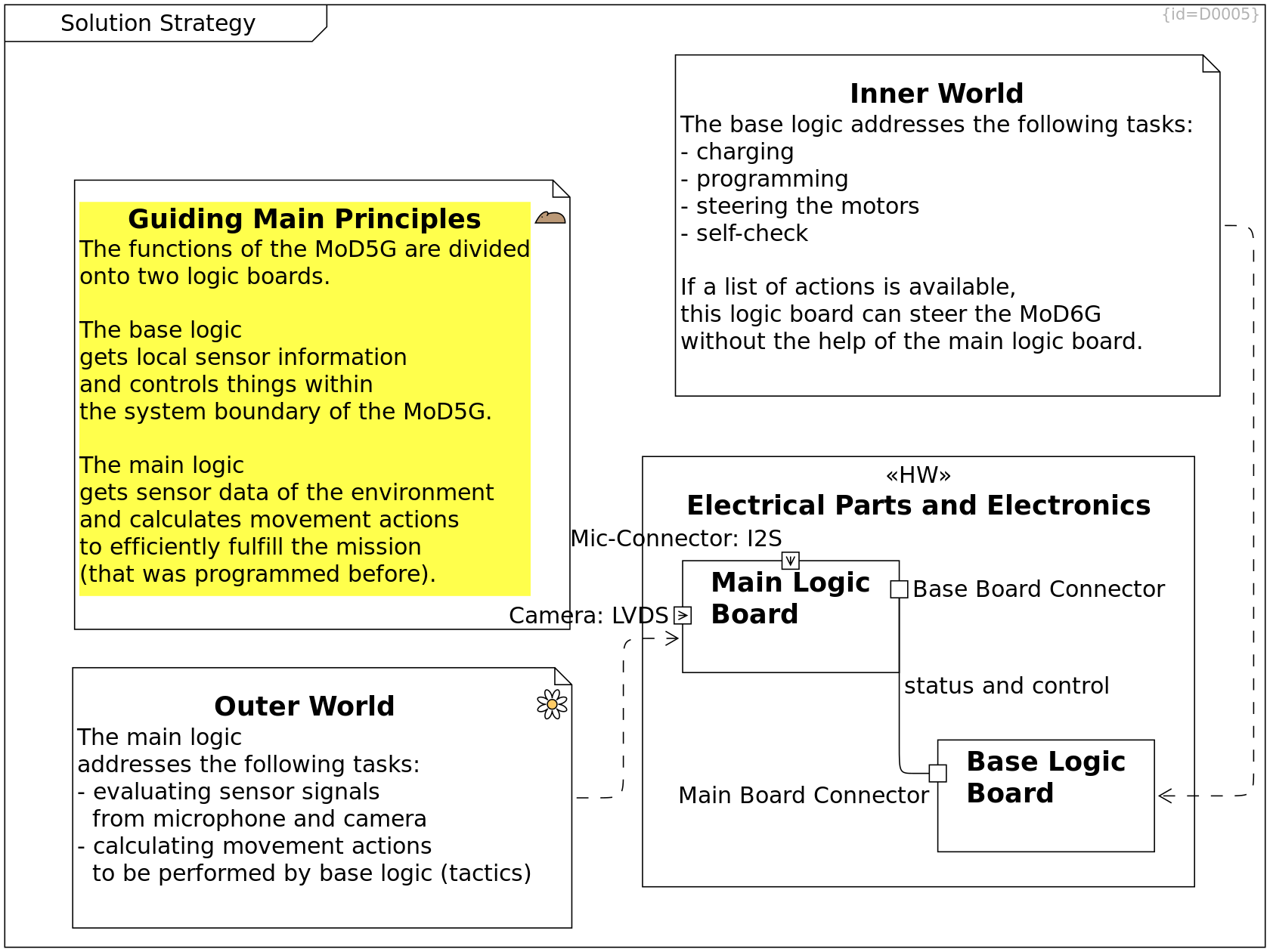
Base Logic Board, Requirements, Failure Modes of Base Logic Board, Inner World, Solution Strategy, Physical View, Risks, Electric Parts and Electronics, Power Distribution
Base Logic Board Block C0048
The base logic board consists of several electronic parts shown in Base Logic Board.
It provides functionality to detect health status of MoD5G components, it steers motors.
main board connector Port F0031
speaker connector Output Port F0049
diagnostic connector Port F0051
motor connector Output Port F0050
Main Board Logic, Requirements, Outer World, Solution Strategy, Physical View, Electric Parts and Electronics, Power Distribution
Main Logic Board Block C0047
The main logic board consists of several electronic parts shown in Main Board Logic.
base board connector Port F0008
microphone connector Input Port F0002
camera connector Input Port F0001
status and control -- Base Logic Board Communication Path R0280
Solution Strategy
Guiding Main Principles mouse-droid Comment C0116
The functions of the MoD5G are divided onto two logic boards.
The main logic
- gets sensor data of the environment and
- calculates movement actions
to efficiently fulfill the mission
(that was programmed before).
The base logic
- gets system-internal sensor information and
- controls things within the system boundary of the MoD5G.
Outer World
Outer World locigal_form Block Definition Diagram D0060
This diagram explains the separation of responsabilities between base logic board and main logic board. Focus is on the main logic board, for base logic board see Inner World.
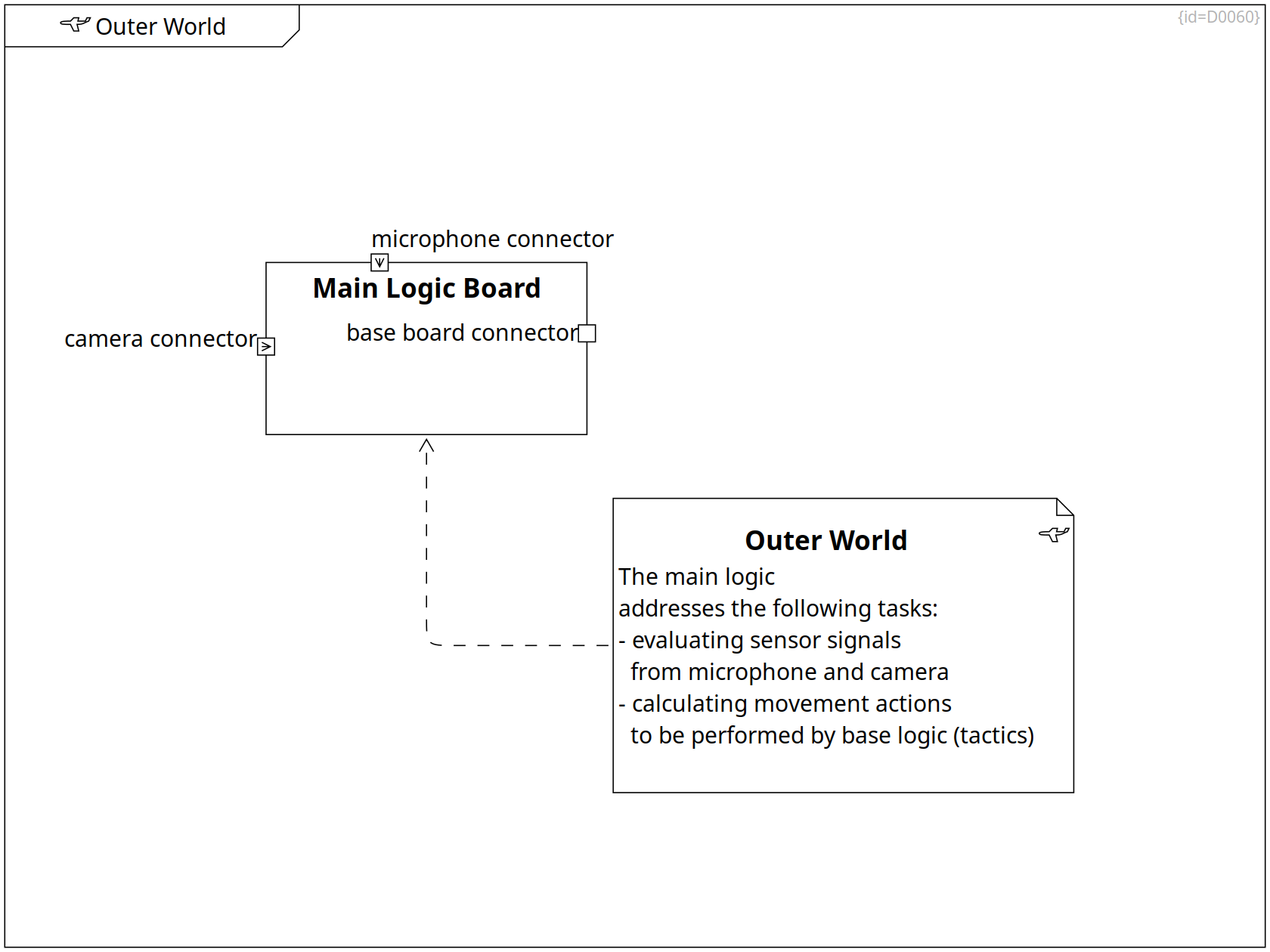
Outer World
Outer World locigal_form Comment C0094
The main logic
addresses the following tasks:
- evaluating sensor signals
from microphone and camera
- calculating movement actions
to be performed by base logic (tactics)
··> Main Logic Board Dependency R0184
Main Board Logic, Requirements, Outer World, Solution Strategy, Physical View, Electric Parts and Electronics, Power Distribution
Main Logic Board Block C0047
The main logic board consists of several electronic parts shown in Main Board Logic.
base board connector Port F0008
microphone connector Input Port F0002
camera connector Input Port F0001
Inner World
Inner World locigal_form Block Definition Diagram D0061
This diagram explains the separation of responsabilities between base logic board and main logic board. Focus is on the base logic board, for main logic board see Outer World.
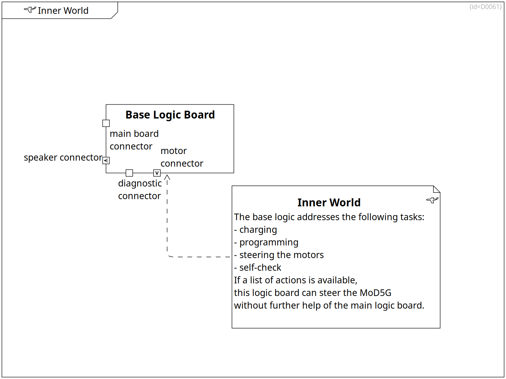
Inner World
Inner World locigal_form Comment C0117
The base logic addresses the following tasks:
- charging
- programming
- steering the motors
- self-check
If a list of actions is available,
this logic board can steer the MoD5G
without further help of the main logic board.
··> Base Logic Board Dependency R0183
Base Logic Board, Requirements, Failure Modes of Base Logic Board, Inner World, Solution Strategy, Physical View, Risks, Electric Parts and Electronics, Power Distribution
Base Logic Board Block C0048
The base logic board consists of several electronic parts shown in Base Logic Board.
It provides functionality to detect health status of MoD5G components, it steers motors.
main board connector Port F0031
speaker connector Output Port F0049
diagnostic connector Port F0051
motor connector Output Port F0050
Functional View
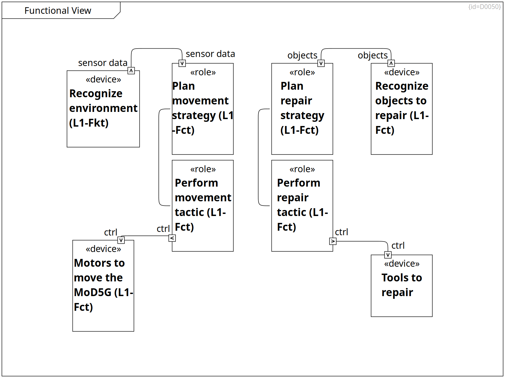
Functional View Block Definition Diagram D0050
This view shows the functionalities of the MoD5G.
Functions represent the solutions to the functional requirements.
It also shows which function produces output that is needed by another function as input.
Sensors (devices) produce output to controller-parts (functions). These functions send their output to other functions or to actuators (devices).
Logical View on Sensors and Actuators, Functional View
Motors to move the MoD5G actuator Block C0178
ctrl Input Port F0041
Logical View on Sensors and Actuators, Functional View
Recognize environment sensor Block C0179
This function aggregates the data of several sensors over time.
It produces a consistent location map of the environment.
sensor data Output Port F0035
-- Plan movement strategy Communication Path R0286
Logical View on Sensors and Actuators, Functional View
Recognize objects to repair sensor Block C0180
This function aggregates the data of several sensors.
It produces a consistent 3D scene of objects which are close by the Mod5G.
objects Output Port F0037
-- Plan repair strategy Communication Path R0287
Functions covering Requirements, Functional View, Logical View, Functionality per movement-related mode
Plan movement strategy function Block C0181
sensor data Input Port F0036
list of way-points Output Port F0078
-- Perform movement tactic Communication Path R0393
Functional View, Logical View, Functionality per tool-related mode
Plan repair strategy function Block C0182
list of tool moves Output Port F0076
objects Input Port F0038
-- Perform repair tactic Communication Path R0392
Functional View, Logical View, Functionality per movement-related mode
Perform movement tactic function Block C0183
list of way-points Input Port F0079
ctrl Output Port F0042
-- Motors to move the MoD5G Communication Path R0290
Functions covering Requirements, Functional View, Logical View, Functionality per tool-related mode
Perform repair tactic function Block C0184
ctrl Output Port F0039
list of tool moves Input Port F0077
-- Tools to repair Communication Path R0291
Logical View on Sensors and Actuators, Functional View
Tools to repair actuator Block C0185
ctrl Input Port F0040
Functions covering Requirements
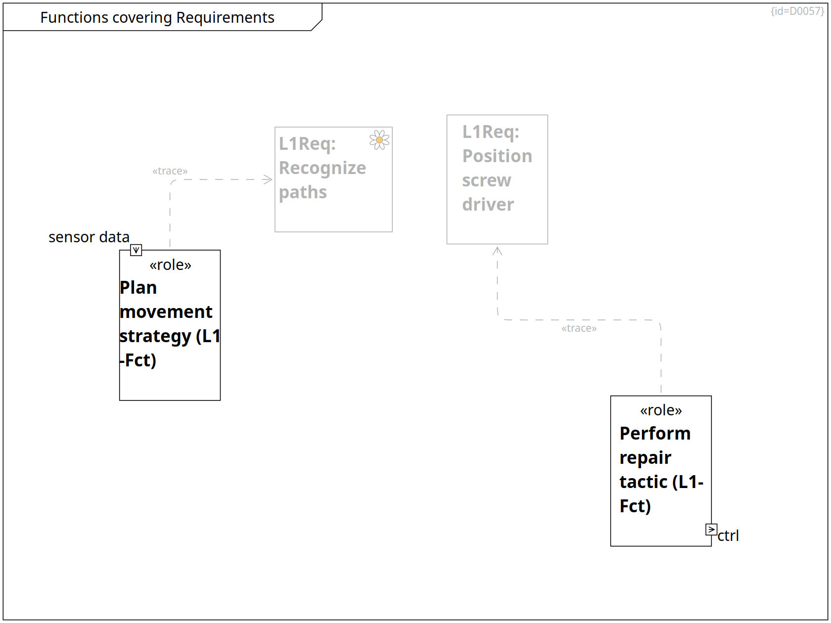
Functions covering Requirements Component Diagram D0057
This diagram shows which function implements/solves which requirements.
Functions covering Requirements, Functional View, Logical View, Functionality per movement-related mode
Plan movement strategy function Block C0181
sensor data Input Port F0036
list of way-points Output Port F0078
··> SYS-Req: Recognize paths Trace R0329
Functions covering Requirements, Functional View, Logical View, Functionality per tool-related mode
Perform repair tactic function Block C0184
ctrl Output Port F0039
list of tool moves Input Port F0077
··> SYS-Req: Position screw driver Trace R0330
Requirements, Functions covering Requirements, Requirements on Tool Usage
SYS-Req: Position screw driver Requirement C0150
The MoDG5 shall bring the screw driver into a given 3D position.
Requirements on Moving, Requirements, Functions covering Requirements
SYS-Req: Recognize paths env-perception Requirement C0149
The MoDG5 shall use redundant sensor data to calculate paths that it can drive along.
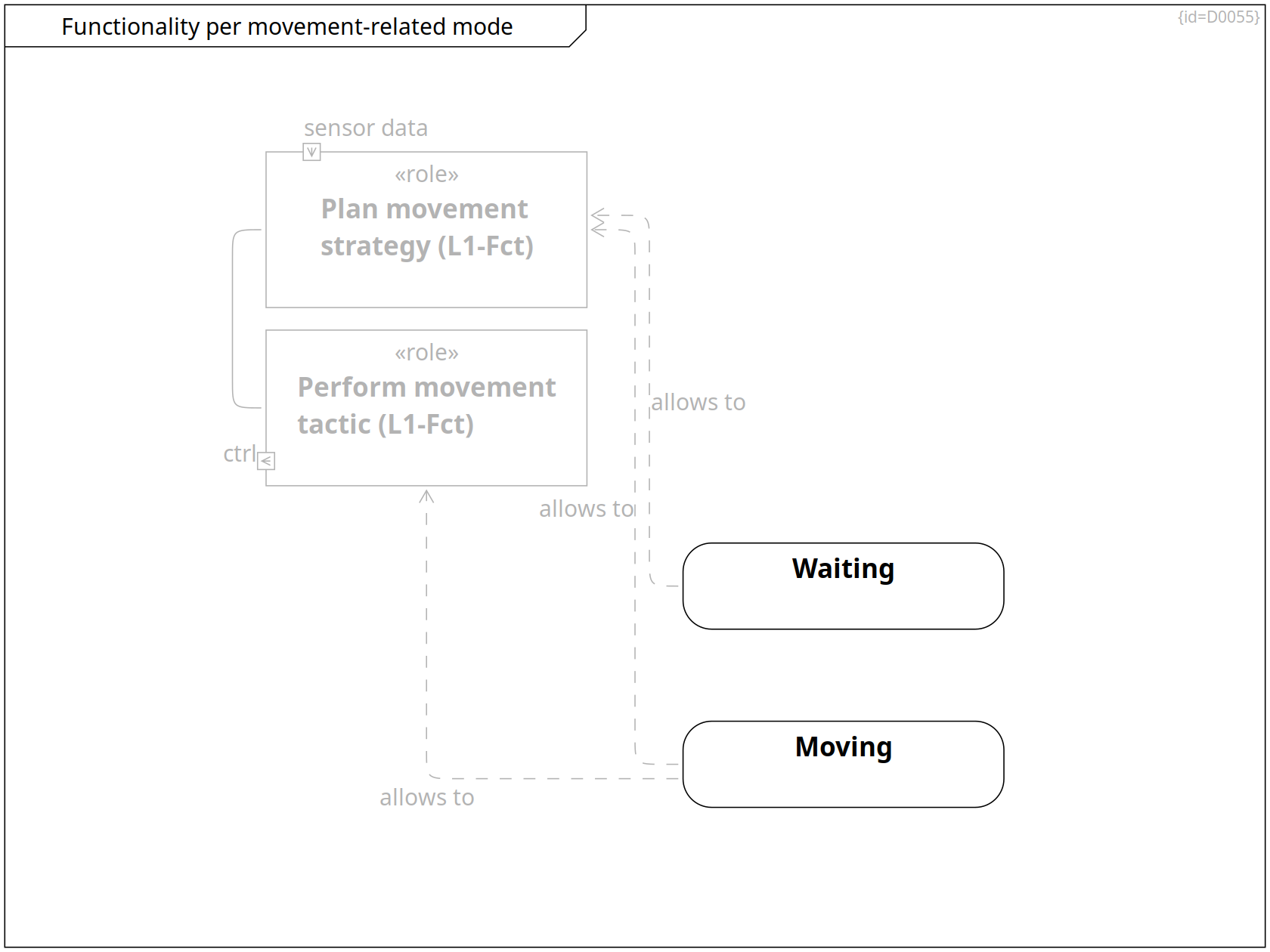
Functionality per movement-related mode
Functionality per movement-related mode State Diagram D0055
This diagram shows the functionalities that are available in the operation modes related to moving.
Functions covering Requirements, Functional View, Logical View, Functionality per movement-related mode
Plan movement strategy function Block C0181
sensor data Input Port F0036
list of way-points Output Port F0078
-- Perform movement tactic Communication Path R0393
Functional View, Logical View, Functionality per movement-related mode
Perform movement tactic function Block C0183
list of way-points Input Port F0079
ctrl Output Port F0042
Operation Modes, Functionality per movement-related mode, Functionality per Mode
Moving State C0191
The moving mode allows to move the MoD5G.
allows to ··> Plan movement strategy Dependency R0311
allows to ··> Perform movement tactic Dependency R0312
Operation Modes, Functionality per movement-related mode, Functionality per tool-related mode, Functionality per Mode
Waiting State C0193
The waiting mode allows to perform nothing till an outside trigger changes the mode.
allows to ··> Plan movement strategy Dependency R0314
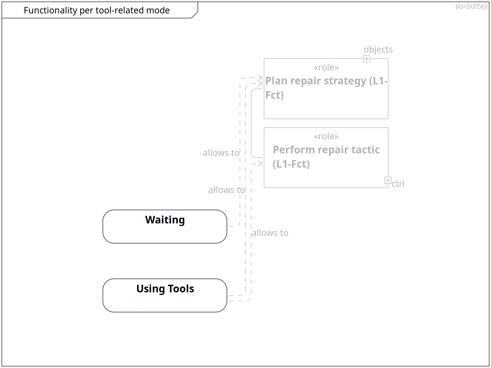
Functionality per tool-related mode
Functionality per tool-related mode State Diagram D0056
This diagram shows the functionalities that are available in the operation modes related to using tools.
Functional View, Logical View, Functionality per tool-related mode
Plan repair strategy function Block C0182
list of tool moves Output Port F0076
objects Input Port F0038
-- Perform repair tactic Communication Path R0392
Functions covering Requirements, Functional View, Logical View, Functionality per tool-related mode
Perform repair tactic function Block C0184
ctrl Output Port F0039
list of tool moves Input Port F0077
Operation Modes, Functionality per tool-related mode, Functionality per Mode
Using Tools State C0192
The using tools mode allows to repair or clean an object at the target location of the programmed mission.
allows to ··> Plan repair strategy Dependency R0309
allows to ··> Perform repair tactic Dependency R0310
Operation Modes, Functionality per movement-related mode, Functionality per tool-related mode, Functionality per Mode
Waiting State C0193
The waiting mode allows to perform nothing till an outside trigger changes the mode.
allows to ··> Plan repair strategy Dependency R0313
Logical View
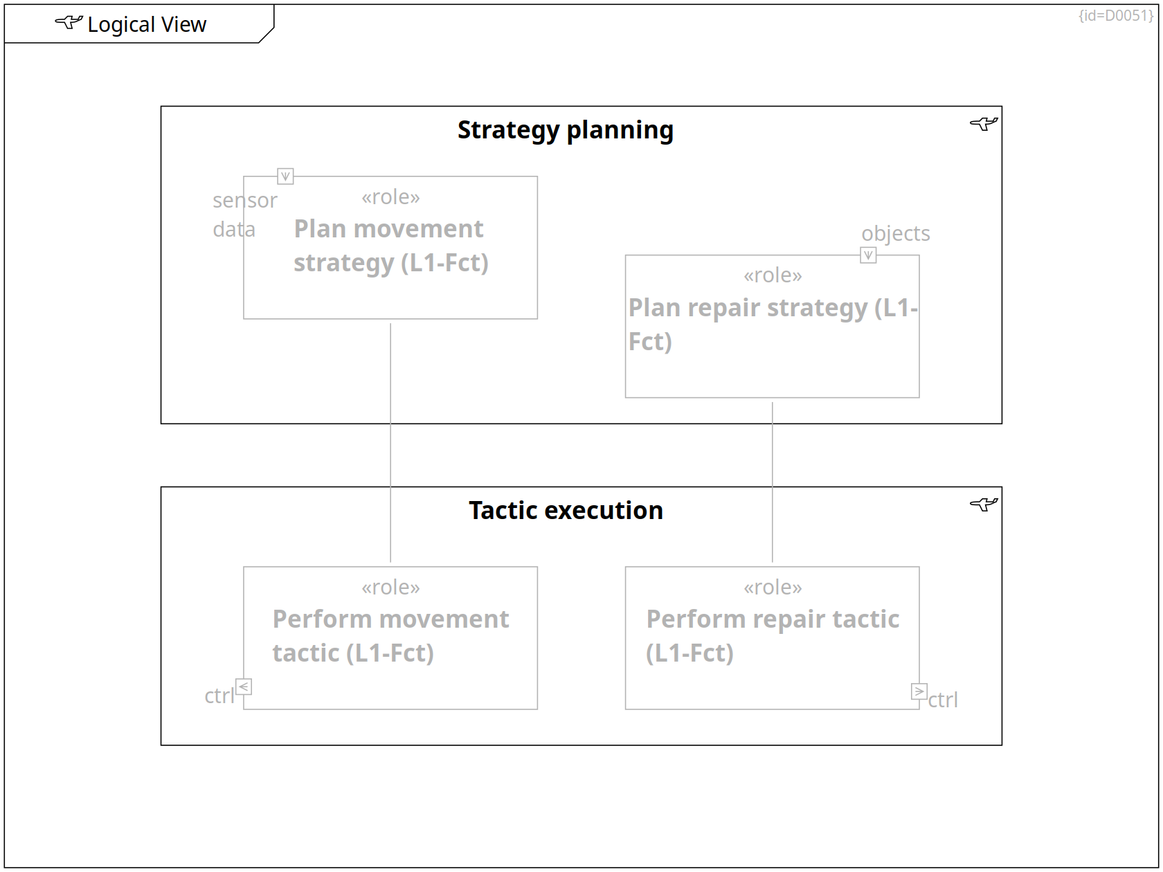
Logical View locigal_form Block Definition Diagram D0051
This view maps the functions to a form.
Functions covering Requirements, Functional View, Logical View, Functionality per movement-related mode
Plan movement strategy function Block C0181
sensor data Input Port F0036
list of way-points Output Port F0078
-- Perform movement tactic Communication Path R0393
Functional View, Logical View, Functionality per tool-related mode
Plan repair strategy function Block C0182
list of tool moves Output Port F0076
objects Input Port F0038
-- Perform repair tactic Communication Path R0392
Functions covering Requirements, Functional View, Logical View, Functionality per tool-related mode
Perform repair tactic function Block C0184
ctrl Output Port F0039
list of tool moves Input Port F0077
Functional View, Logical View, Functionality per movement-related mode
Perform movement tactic function Block C0183
list of way-points Input Port F0079
ctrl Output Port F0042
Logical View, Physical View
Main Strategy Planning locigal_form Block C0186
This system element aggregates functions that have high demands on computation power but less demands on realtime-reactions.
These even may be turned off from time to time.
+-- Plan movement strategy Containment R0292
+-- Plan repair strategy Containment R0293
Logical View, Physical View
Base Tactic Execution locigal_form Block C0187
This system element aggregates functions that have high demands on realtime observations and reactions; also high demands on availability.
+-- Perform movement tactic Containment R0294
+-- Perform repair tactic Containment R0295
Logical View on Sensors and Actuators
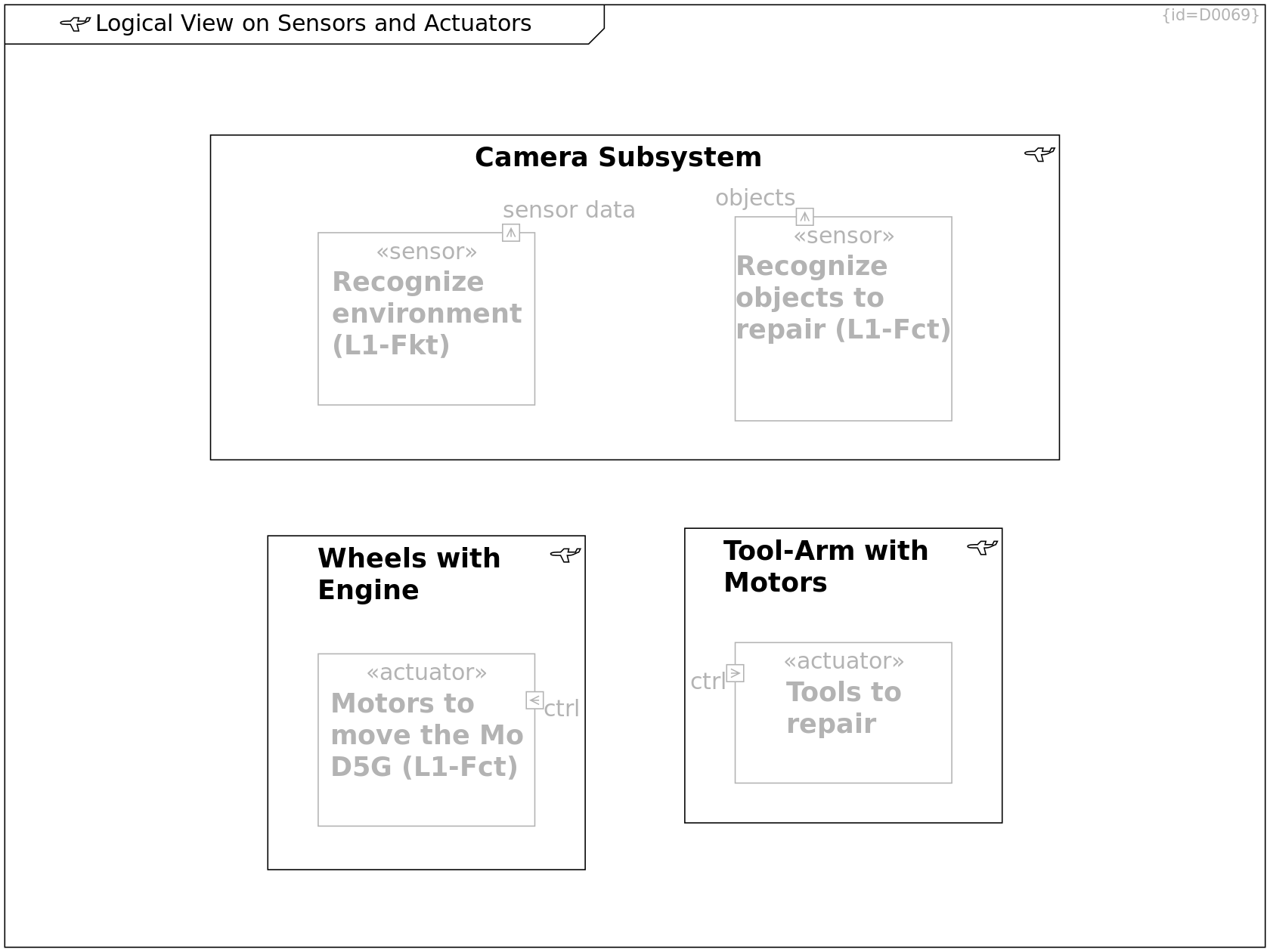
Logical View on Sensors and Actuators locigal_form Block Definition Diagram D0069
The functions identified in Functional View are allocated to locical blocks.
Logical View on Sensors and Actuators
Wheels with Engine locigal_form Block C0220
+-- Motors to move the MoD5G Containment R0400
Logical View on Sensors and Actuators
Tool-Arm with Motors locigal_form Component C0221
locigal_form
+-- Tools to repair Containment R0398
Logical View on Sensors and Actuators
Camera Subsystem locigal_form Block C0222
+-- Recognize environment Containment R0397
+-- Recognize objects to repair Containment R0399
Logical View on Sensors and Actuators, Functional View
Recognize environment sensor Block C0179
This function aggregates the data of several sensors over time.
It produces a consistent location map of the environment.
sensor data Output Port F0035
Logical View on Sensors and Actuators, Functional View
Motors to move the MoD5G actuator Block C0178
ctrl Input Port F0041
Logical View on Sensors and Actuators, Functional View
Tools to repair actuator Block C0185
ctrl Input Port F0040
Logical View on Sensors and Actuators, Functional View
Recognize objects to repair sensor Block C0180
This function aggregates the data of several sensors.
It produces a consistent 3D scene of objects which are close by the Mod5G.
objects Output Port F0037
Physical View
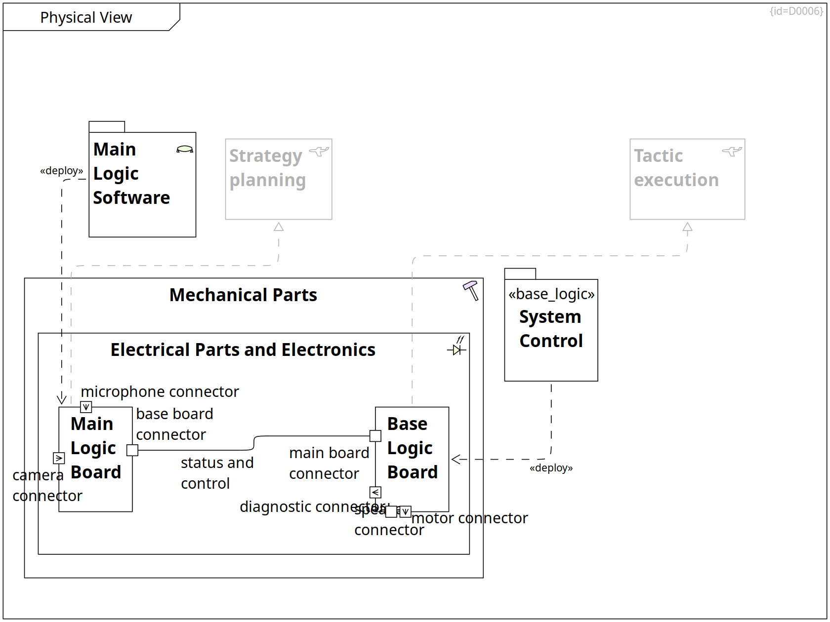
Physical View Block Definition Diagram D0006
This view maps the logical form to physical artifacts. These are mechanical, electronic or software parts.
(Solution Space, System Level)
Mechanics, Physical View
Mechanical Parts HW Block C0018
The mechanical parts encompass all parts of which the mouse droid consists.
From outside, the chassis and wheels are the most obvious parts.
Inside, a skeleton frame provides stability of the assembly.
Important characteristics are weight, operating temperature range, durability, stability.
+-- Electronics Containment R0013
Mechanics, Physical View, Electric Parts and Electronics
Electronics EE Block C0019
The main components of the electric parts are:
- a set of cables and connectors
- a set of sensors and actuators
- the energy cell
- two printed circuit boards (PCB) containing the electronics
+-- Base Logic Board Containment R0048
+-- Main Logic Board Containment R0047
Solution Strategy, Physical View, Building Block View
Main Logic Software SW Package C0020
The software consists of control logic, initial data that was integrated at the factory and learned data that is aggregated during operation.
These software items are split over two logical boards and subdivided into independent execution partitions.
··> Main Logic Board Deployment R0348
Main Board Logic, Requirements, Outer World, Solution Strategy, Physical View, Electric Parts and Electronics, Power Distribution
Main Logic Board Block C0047
The main logic board consists of several electronic parts shown in Main Board Logic.
base board connector Port F0008
microphone connector Input Port F0002
camera connector Input Port F0001
status and control -- Base Logic Board Communication Path R0280
··|> Main Strategy Planning Realization R0296
Base Logic Board, Requirements, Failure Modes of Base Logic Board, Inner World, Solution Strategy, Physical View, Risks, Electric Parts and Electronics, Power Distribution
Base Logic Board Block C0048
The base logic board consists of several electronic parts shown in Base Logic Board.
It provides functionality to detect health status of MoD5G components, it steers motors.
main board connector Port F0031
speaker connector Output Port F0049
diagnostic connector Port F0051
motor connector Output Port F0050
··|> Base Tactic Execution Realization R0297
Logical View, Physical View
Main Strategy Planning locigal_form Block C0186
This system element aggregates functions that have high demands on computation power but less demands on realtime-reactions.
These even may be turned off from time to time.
Logical View, Physical View
Base Tactic Execution locigal_form Block C0187
This system element aggregates functions that have high demands on realtime observations and reactions; also high demands on availability.
System Control, Solution Strategy, Physical View, Building Block View, Deployment View
Base System Control base_logic Package C0119
··> Base Logic Board Deployment R0349
Mechanics
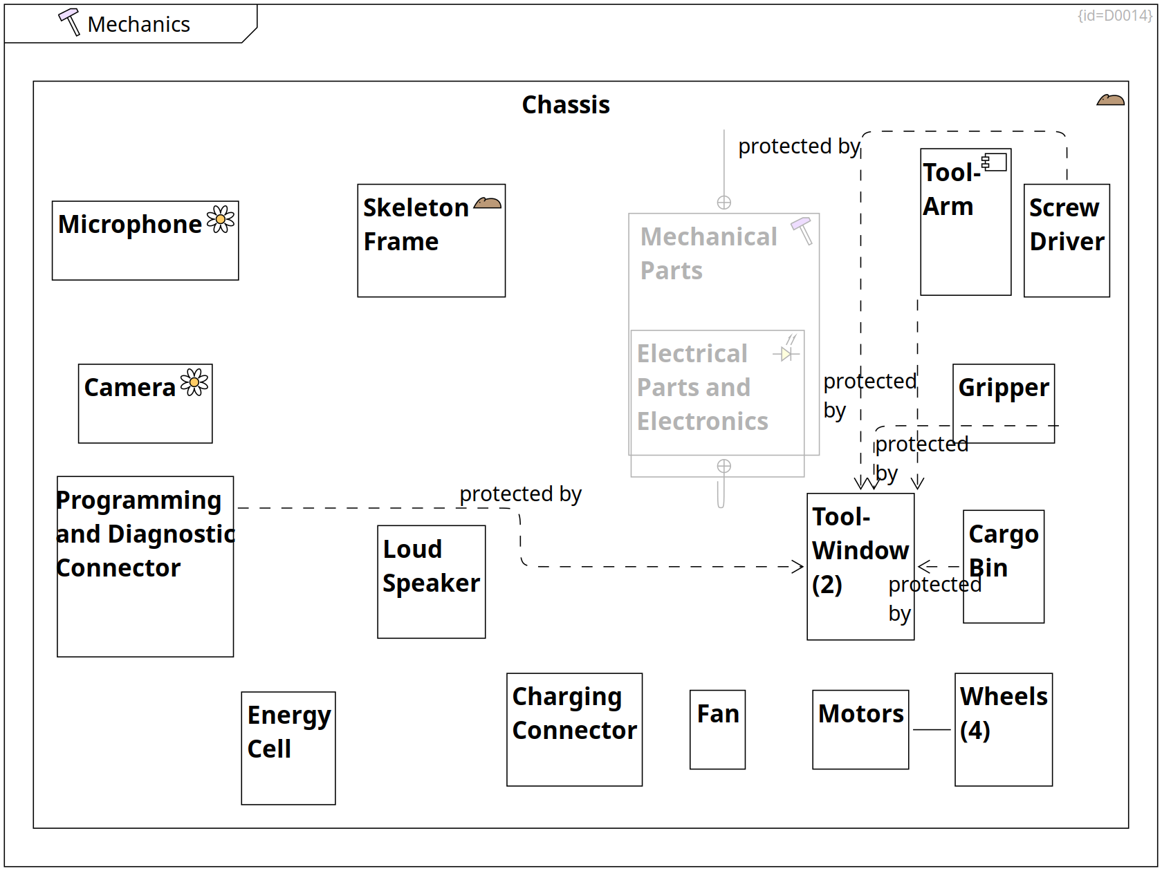
Mechanics HW Component Diagram D0014
This section shows the mechanical parts of the MoD5G system (Solution Space)
Mechanics
Cargo Bin Block C0036
A cargo bin allows to transport replacement parts to repair remote systems.
protected by ··> Tool-Window (2) Dependency R0224
Mechanics, Requirements
Screw Driver Block C0037
A screw driver can rotate screws. It is one of several tools fixed on top of the Tool-Arm.
protected by ··> Tool-Window (2) Dependency R0225
Mechanics, Risks, Failure Modes of Motors and Wheels
Wheels (4) Block C0038
The functionality of wheels is to transform a torque force into movement of the MoD5G.
Mechanics
Fan Block C0039
A fan prevents overheating in hot environment conditions.
Mechanics, Risks, Failure Modes of Motors and Wheels, Electric Parts and Electronics
Motors Block C0040
There are two motors to drive and steer and further motors to control the movement of a tool-arm.
-- Wheels (4) Communication Path R0332
Mechanics, Requirements, Electric Parts and Electronics
Camera env-perception Block C0041
A camera records the video signal of the environment.
Mechanics, Electric Parts and Electronics
Microphone env-perception Block C0042
A microphone records the audio signal of the environment.
Mechanics, Electric Parts and Electronics
Loud Speaker Block C0043
A loud speaker allows to produce single-frequency audio signals.
Mechanics, Electric Parts and Electronics
Programming and Diagnostic Connector Block C0044
A connector allows to attach a cable. Via this cable, self diagnosis and re-programming can be performed.
protected by ··> Tool-Window (2) Dependency R0226
Mechanics, Power Distribution
Charging Connector Block C0045
A connector allows to attach a cable. Via this cable, the energy cell can be re-charged.
Failure Modes of Energy Cell, Mechanics, Risks, Power Distribution
Energy Cell Block C0046
An energy cell provides power sufficient for a 1-day mission.
Mechanics, Physical View
Mechanical Parts HW Block C0018
The mechanical parts encompass all parts of which the mouse droid consists.
From outside, the chassis and wheels are the most obvious parts.
Inside, a skeleton frame provides stability of the assembly.
Important characteristics are weight, operating temperature range, durability, stability.
+-- Electronics Containment R0013
+-- Skeleton Frame Containment R0405
+-- Microphone Containment R0406
+-- Camera Containment R0407
+-- Programming and Diagnostic Connector Containment R0408
+-- Tool-Arm Containment R0409
+-- Tool-Window (2) Containment R0410
+-- Screw Driver Containment R0411
+-- Gripper Containment R0412
+-- Cargo Bin Containment R0413
+-- Wheels (4) Containment R0414
+-- Motors Containment R0415
+-- Fan Containment R0416
+-- Charging Connector Containment R0417
+-- Loud Speaker Containment R0418
+-- Energy Cell Containment R0419
Mechanics, Physical View, Electric Parts and Electronics
Electronics EE Block C0019
The main components of the electric parts are:
- a set of cables and connectors
- a set of sensors and actuators
- the energy cell
- two printed circuit boards (PCB) containing the electronics
Mechanics
Gripper Block C0054
A tool that allows to grab objects and move them. It is one of several tools fixed on top of the Tool-Arm.
protected by ··> Tool-Window (2) Dependency R0223
Mechanics
Tool-Window (2) Block C0055
A tool window is a flap in the chassis that protects screw driver, gripper and cargo bin when unused.
It can be opened and closed by a motor.
Mechanics
Skeleton Frame mouse-droid Block C0146
The skeleton frame provides stability to the assembly of parts.
Anchorage points latch the assembled parts at their positions.
Mechanics
Tool-Arm Component C0202
An arm consisting of two segments.
The angle between the segments provides 1 degree of movement freedom, both ends provide 2 degrees of movement freedom each.
protected by ··> Tool-Window (2) Dependency R0328
Electric Parts and Electronics
Electric Parts and Electronics EE Block Definition Diagram D0018
This section shows the electric parts and electronics of the MoD5G system (Solution Space)
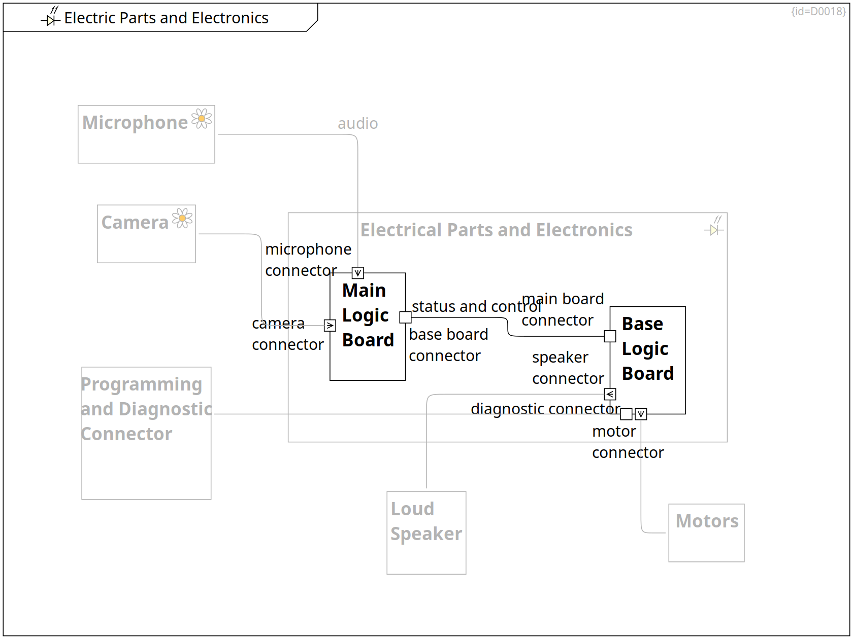
Mechanics, Physical View, Electric Parts and Electronics
Electronics EE Block C0019
The main components of the electric parts are:
- a set of cables and connectors
- a set of sensors and actuators
- the energy cell
- two printed circuit boards (PCB) containing the electronics
+-- Base Logic Board Containment R0048
+-- Main Logic Board Containment R0047
Mechanics, Electric Parts and Electronics
Loud Speaker Block C0043
A loud speaker allows to produce single-frequency audio signals.
Mechanics, Requirements, Electric Parts and Electronics
Camera env-perception Block C0041
A camera records the video signal of the environment.
-- Main Logic Board Communication Path R0051
Mechanics, Electric Parts and Electronics
Microphone env-perception Block C0042
A microphone records the audio signal of the environment.
audio -- Main Logic Board Communication Path R0056
Mechanics, Risks, Failure Modes of Motors and Wheels, Electric Parts and Electronics
Motors Block C0040
There are two motors to drive and steer and further motors to control the movement of a tool-arm.
Mechanics, Electric Parts and Electronics
Programming and Diagnostic Connector Block C0044
A connector allows to attach a cable. Via this cable, self diagnosis and re-programming can be performed.
Main Board Logic, Requirements, Outer World, Solution Strategy, Physical View, Electric Parts and Electronics, Power Distribution
Main Logic Board Block C0047
The main logic board consists of several electronic parts shown in Main Board Logic.
base board connector Port F0008
microphone connector Input Port F0002
camera connector Input Port F0001
status and control -- Base Logic Board Communication Path R0280
Base Logic Board, Requirements, Failure Modes of Base Logic Board, Inner World, Solution Strategy, Physical View, Risks, Electric Parts and Electronics, Power Distribution
Base Logic Board Block C0048
The base logic board consists of several electronic parts shown in Base Logic Board.
It provides functionality to detect health status of MoD5G components, it steers motors.
main board connector Port F0031
speaker connector Output Port F0049
diagnostic connector Port F0051
motor connector Output Port F0050
-- Loud Speaker Communication Path R0322
-- Programming and Diagnostic Connector Communication Path R0324
-- Motors Communication Path R0326
Crosscutting Concepts, Electric Parts and Electronics
Step Motor Comment C0218
All motors are electrical step motors.
··> Motors Dependency R0396
Base Logic Board
Base Logic Board Internal Block Diagram D0035
This section shows the base board logic of the MoD5G system (Solution Space, EE Level)
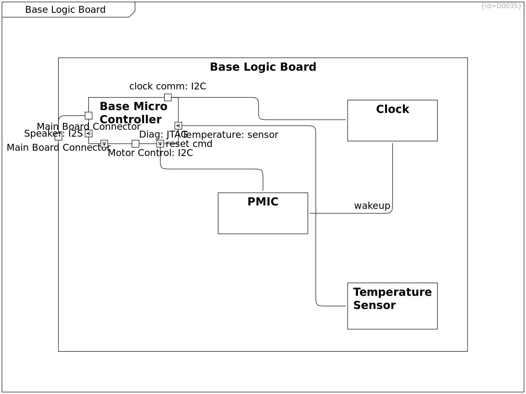
Base Logic Board, Requirements, Failure Modes of Base Logic Board, Inner World, Solution Strategy, Physical View, Risks, Electric Parts and Electronics, Power Distribution
Base Logic Board Block C0048
The base logic board consists of several electronic parts shown in Base Logic Board.
It provides functionality to detect health status of MoD5G components, it steers motors.
main board connector Port F0031
speaker connector Output Port F0049
diagnostic connector Port F0051
motor connector Output Port F0050
+-- Base Micro Controller Containment R0053
+-- Clock Containment R0055
+-- PMIC Containment R0049
+-- Temperature Sensor Containment R0095
-- Base Micro Controller Communication Path R0279
Base Logic Board, Requirements and Goals, Software [subsystem]
Base Micro Controller Block C0051
The base micro controller consists of
- logic unit
- data storage
- persistent data+logic storage
- self supervision (by ECC and lockstep-cores)
- HW watchdog
- clock
- temperature sensor
- io ports
This block is optimized for providing a reliable execution of algorithms, see Quality Requirements.
temperature Input Port F0010
clock comm Port F0007
main board connector Port F0009
speaker Output Port F0004
diagnostic port Port F0005
motor control Output Port F0003
reset cmd Output Port F0006
-- PMIC Communication Path R0062
-- Clock Communication Path R0066
-- Base Logic Board Communication Path R0321
-- Base Logic Board Communication Path R0323
-- Base Logic Board Communication Path R0325
Base Logic Board
Clock Block C0053
The clock tells the current time. An alarm can be set that will cause a wakeup event to the PMIC.
wakeup -- PMIC Communication Path R0067
Base Logic Board
Temperature Sensor Block C0071
-- Base Micro Controller Communication Path R0096
Main Board Logic
Main Board Logic Internal Block Diagram D0022
This section shows the main board logic of the MoD5G system (Solution Space, EE Level)
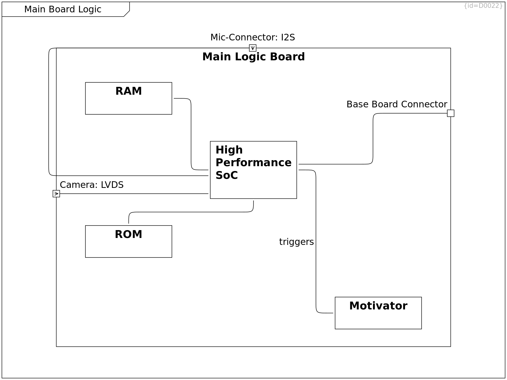
Main Board Logic, Requirements, Outer World, Solution Strategy, Physical View, Electric Parts and Electronics, Power Distribution
Main Logic Board Block C0047
The main logic board consists of several electronic parts shown in Main Board Logic.
base board connector Port F0008
microphone connector Input Port F0002
camera connector Input Port F0001
+-- RAM Containment R0070
+-- ROM Containment R0071
+-- Main Performance Controller Containment R0069
+-- Motivator Containment R0077
-- Main Performance Controller Communication Path R0074
-- Main Performance Controller Communication Path R0076
Main Board Logic, Requirements and Goals, Software [subsystem]
Main Performance Controller Block C0056
This block provides an execution environment for algorithms that is optimized for high performance.
-- RAM Communication Path R0072
-- ROM Communication Path R0073
-- Main Logic Board Communication Path R0075
Main Board Logic
RAM Block C0057
Main Board Logic
ROM Block C0058
Main Board Logic
Motivator Block C0059
A motivator is a basic component needed to keep going on.
triggers -- Main Performance Controller Communication Path R0078
Power Distribution
Power Distribution Block Definition Diagram D0054
This section shows the electric parts and electronics of the MoD5G system (Solution Space, System Level)
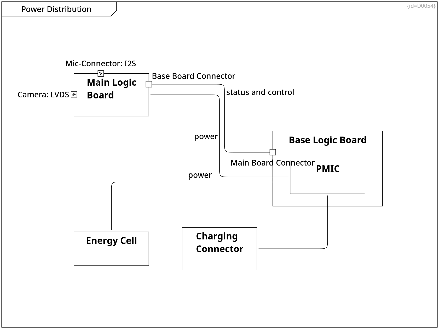
power -- Main Logic Board Communication Path R0063
Mechanics, Power Distribution
Charging Connector Block C0045
A connector allows to attach a cable. Via this cable, the energy cell can be re-charged.
-- PMIC Communication Path R0057
Failure Modes of Energy Cell, Mechanics, Risks, Power Distribution
Energy Cell Block C0046
An energy cell provides power sufficient for a 1-day mission.
power -- PMIC Communication Path R0050
Main Board Logic, Requirements, Outer World, Solution Strategy, Physical View, Electric Parts and Electronics, Power Distribution
Main Logic Board Block C0047
The main logic board consists of several electronic parts shown in Main Board Logic.
base board connector Port F0008
microphone connector Input Port F0002
camera connector Input Port F0001
status and control -- Base Logic Board Communication Path R0280
Base Logic Board, Requirements, Failure Modes of Base Logic Board, Inner World, Solution Strategy, Physical View, Risks, Electric Parts and Electronics, Power Distribution
Base Logic Board Block C0048
The base logic board consists of several electronic parts shown in Base Logic Board.
It provides functionality to detect health status of MoD5G components, it steers motors.
main board connector Port F0031
speaker connector Output Port F0049
diagnostic connector Port F0051
motor connector Output Port F0050
+-- PMIC Containment R0049
Software [subsystem]
Software [subsystem] SW Deployment Diagram D0019
This diagram shows the virtual machines and specialized (non-versatile) execution environments (Solution Space)
These are deployed onto the logic boards shown in Electric Parts and Electronics.
In this section, this view is further detailed to software elements, their relations and interactions.
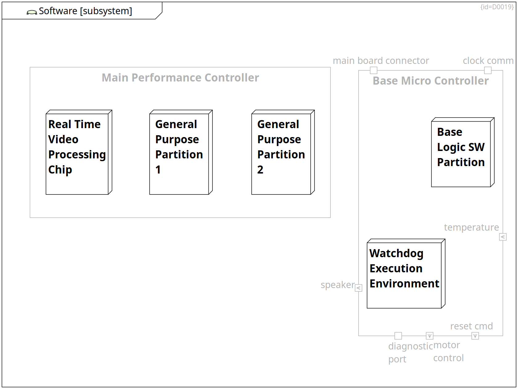
Main Board Logic, Requirements and Goals, Software [subsystem]
Main Performance Controller Block C0056
This block provides an execution environment for algorithms that is optimized for high performance.
+-- Real Time Video Processing Chip Containment R0079
+-- General Purpose Partition 1 Containment R0081
+-- General Purpose Partition 2 Containment R0082
Base Logic Board, Requirements and Goals, Software [subsystem]
Base Micro Controller Block C0051
The base micro controller consists of
- logic unit
- data storage
- persistent data+logic storage
- self supervision (by ECC and lockstep-cores)
- HW watchdog
- clock
- temperature sensor
- io ports
This block is optimized for providing a reliable execution of algorithms, see Quality Requirements.
temperature Input Port F0010
clock comm Port F0007
main board connector Port F0009
speaker Output Port F0004
diagnostic port Port F0005
motor control Output Port F0003
reset cmd Output Port F0006
+-- Base Logic SW Partition Containment R0083
+-- Watchdog Execution Environment Containment R0080
Deployment View, Software [subsystem]
Real Time Video Processing Chip Node C0060
Software [subsystem]
Watchdog Execution Environment Node C0061
Deployment View, Software [subsystem]
General Purpose Partition 1 Node C0062
Deployment View, Software [subsystem]
General Purpose Partition 2 Node C0063
Deployment View, Software [subsystem]
Base Logic SW Partition Node C0064
Requirements and Goals
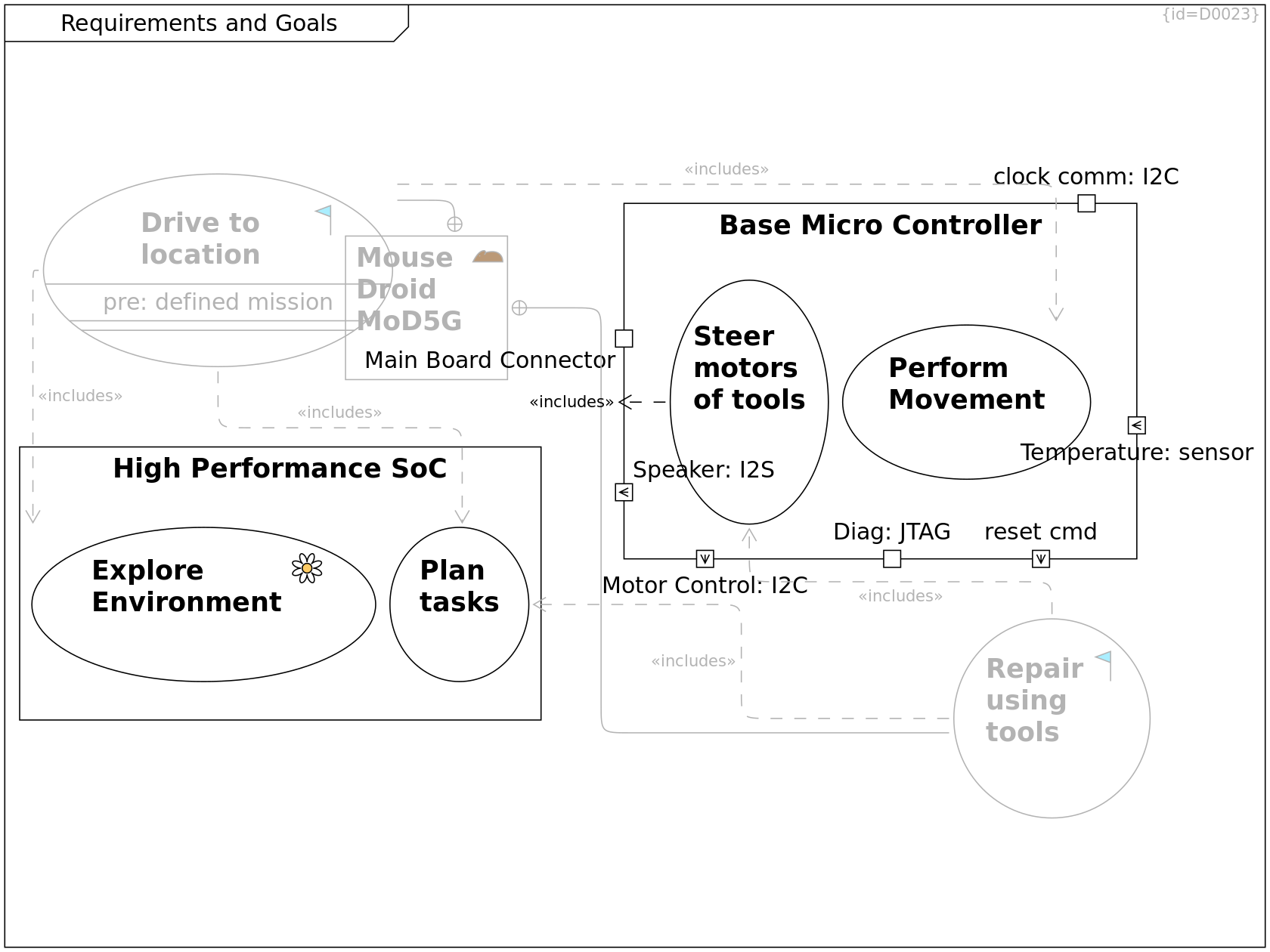
Requirements and Goals Use Case Diagram D0023
This section shows the goals of the software development for the MoD5G (Problem Space, Software Level)
In gray, the use cases on system level are repeated from Use Cases and Requirements.
In black, the refinement to software-only use cases is presented.
Scope and Context, Use Cases and Requirements, Factory Context, Requirements and Goals, Operational Context, Scope and Context, Deployment View
Mouse Droid MoD5G mouse-droid Subsystem C0004
The Mouse Droid (MoD5G) is a repair droid that can be instructed to perform a mission and which then autonomously selects tactics to achieve the mission goals.
charge connector Port F0074
Via the charge connector, the energy call can be refreshed.
program connector Port F0075
Via the program connector, an operator provides the data for a mission to be performed.
+-- Drive to location Containment R0003
+-- Repair using tools Containment R0004
Use Cases and Requirements, Requirements and Goals, Requirements on Moving, Functionality per Mode
Drive to location goal Use Case C0007
The mouse droid can explore its environment and calculate a route from its actual position to the target location.
- The mouse droid explores its environment
- The mouse droid enriches an internally memorized map
- The mouse droid calculates a route
- The mouse droid drives along the calculated route
- The mouse droid re-caclulates the route in case of new environment data
- The mouse droid reaches the target location
pre: mission is defined Property F0032
post: MoD5G is at target location Property F0043
··> Plan tasks Inclusion R0091
··> Explore environment Inclusion R0234
··> Perform movement Inclusion R0235
Use Cases and Requirements, Requirements and Goals, Requirements on Tool Usage, Functionality per Mode
Repair using tools goal Use Case C0008
The mouse droid has a couple of tools inside its chassis.
- The mouse droid uses a screw diver to untighten damaged parts
- The mouse droid uses a gripper to move the damaged part out of the way
- The mouse droid uses a gripper to put a spare part from its internal cargo bin to the target place
- The mouse droid uses a screw diver to tighten replaced parts
- The mouse droid uses a gripper to move the damaged part into its internal cargo bin.
(see Mechanics)
pre: MoD5G is at target location Property F0044
··> Plan tasks Inclusion R0090
··> Operate tools Inclusion R0233
Requirements and Goals, Requirements
Explore environment env-perception Use Case C0067
When the mouse droid is missing relevant data on the environment, it plans a list of actions that suits the purpose of gaining the missing knowledge.
Requirements and Goals
Perform movement Use Case C0068
Requirements and Goals, Requirements
Operate tools Use Case C0069
Requirements and Goals
Plan tasks Use Case C0070
The mouse droid creates a list of actions to fulfill the given mission.
If data on the environment is missing, it plans an explortion task and re-plans the action list later.
Main Board Logic, Requirements and Goals, Software [subsystem]
Main Performance Controller Block C0056
This block provides an execution environment for algorithms that is optimized for high performance.
+-- Explore environment Containment R0258
+-- Plan tasks Containment R0259
Base Logic Board, Requirements and Goals, Software [subsystem]
Base Micro Controller Block C0051
The base micro controller consists of
- logic unit
- data storage
- persistent data+logic storage
- self supervision (by ECC and lockstep-cores)
- HW watchdog
- clock
- temperature sensor
- io ports
This block is optimized for providing a reliable execution of algorithms, see Quality Requirements.
temperature Input Port F0010
clock comm Port F0007
main board connector Port F0009
speaker Output Port F0004
diagnostic port Port F0005
motor control Output Port F0003
reset cmd Output Port F0006
+-- Operate tools Containment R0256
+-- Perform movement Containment R0257
Requirements
Requirements Requirement Diagram D0045
This diagram shows the software level requirements.
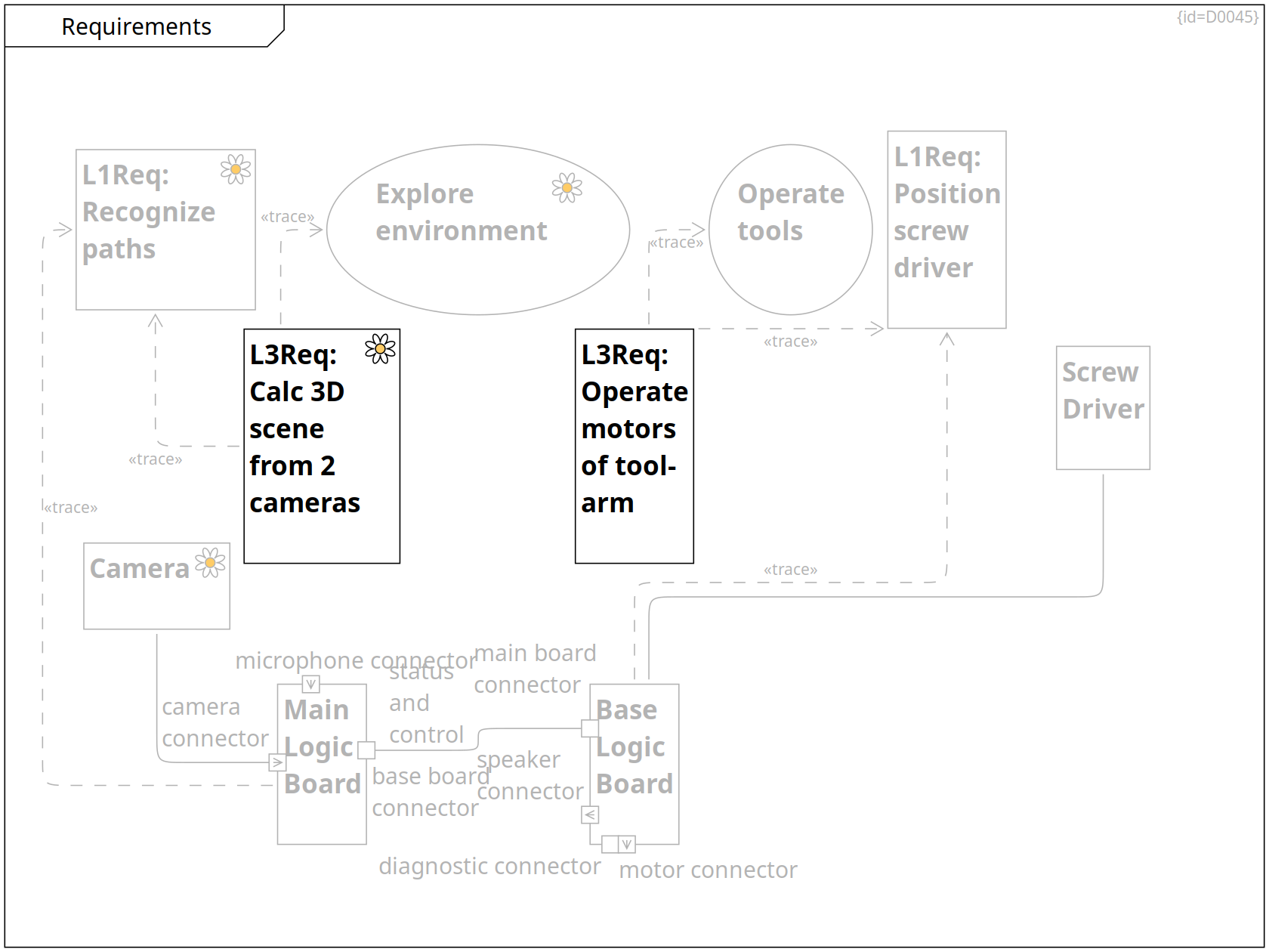
Requirements on Moving, Requirements, Functions covering Requirements
SYS-Req: Recognize paths env-perception Requirement C0149
The MoDG5 shall use redundant sensor data to calculate paths that it can drive along.
Requirements, Functions covering Requirements, Requirements on Tool Usage
SYS-Req: Position screw driver Requirement C0150
The MoDG5 shall bring the screw driver into a given 3D position.
Requirements and Goals, Requirements
Explore environment env-perception Use Case C0067
When the mouse droid is missing relevant data on the environment, it plans a list of actions that suits the purpose of gaining the missing knowledge.
Requirements and Goals, Requirements
Operate tools Use Case C0069
Requirements, Environment Capture
SW-Req: Calc 3D scene from 2 cameras env-perception Requirement C0151
The Main Logic Board shall create a 3D model of the environment based on 2 camera images.
··> Explore environment Trace R0248
··> SYS-Req: Recognize paths Trace R0249
Base Logic Board, Requirements, Failure Modes of Base Logic Board, Inner World, Solution Strategy, Physical View, Risks, Electric Parts and Electronics, Power Distribution
Base Logic Board Block C0048
The base logic board consists of several electronic parts shown in Base Logic Board.
It provides functionality to detect health status of MoD5G components, it steers motors.
main board connector Port F0031
speaker connector Output Port F0049
diagnostic connector Port F0051
motor connector Output Port F0050
··> SYS-Req: Position screw driver Trace R0247
-- Screw Driver Communication Path R0252
Main Board Logic, Requirements, Outer World, Solution Strategy, Physical View, Electric Parts and Electronics, Power Distribution
Main Logic Board Block C0047
The main logic board consists of several electronic parts shown in Main Board Logic.
base board connector Port F0008
microphone connector Input Port F0002
camera connector Input Port F0001
··> SYS-Req: Recognize paths Trace R0246
status and control -- Base Logic Board Communication Path R0280
Requirements, System Control
SW-Req: Operate motors of tool-arm Requirement C0152
The Base Logic Board shall steer the motors of the tool-arm to a given 3D position.
··> SYS-Req: Position screw driver Trace R0250
··> Operate tools Trace R0251
Mechanics, Requirements
Screw Driver Block C0037
A screw driver can rotate screws. It is one of several tools fixed on top of the Tool-Arm.
Mechanics, Requirements, Electric Parts and Electronics
Camera env-perception Block C0041
A camera records the video signal of the environment.
-- Main Logic Board Communication Path R0051
Constraints
Constraints Requirement Diagram D0024
This section explains the major obstacles, that need to be considered when designing a solution to reach the project goals. (Problem Space, Software Level)
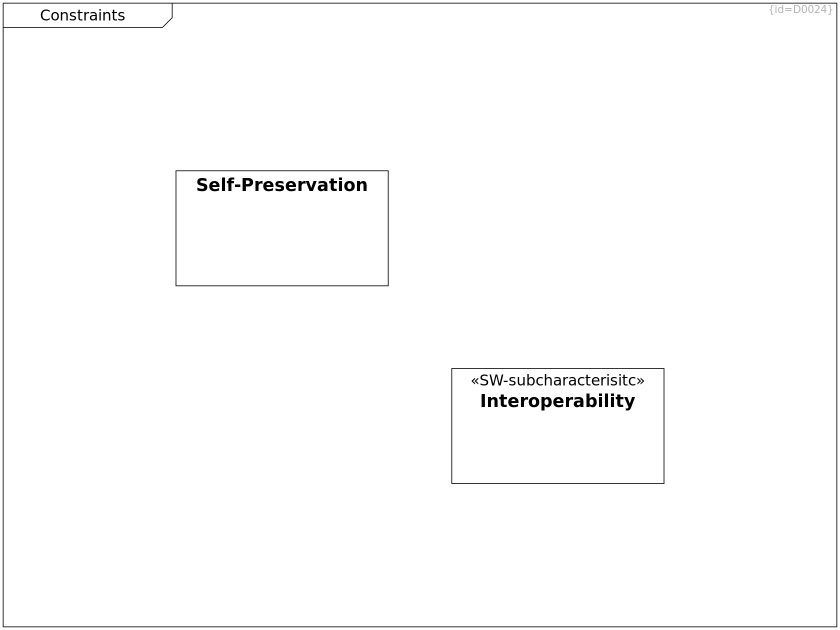
Constraints, Architecture Decisions
Self-Preservation Requirement C0081
In case a wookiee growls at the MoD5G,
it shall flee for self-preservation
Quality Tree, Constraints, Quality Scenarios, Quality Requirements
Interoperability SW-subcharacterisitc Requirement C0123
The programming and charging interfaces
of the MoD5G shall be compatible to
- old republic terminals
- imperial terminals
Scope and Context
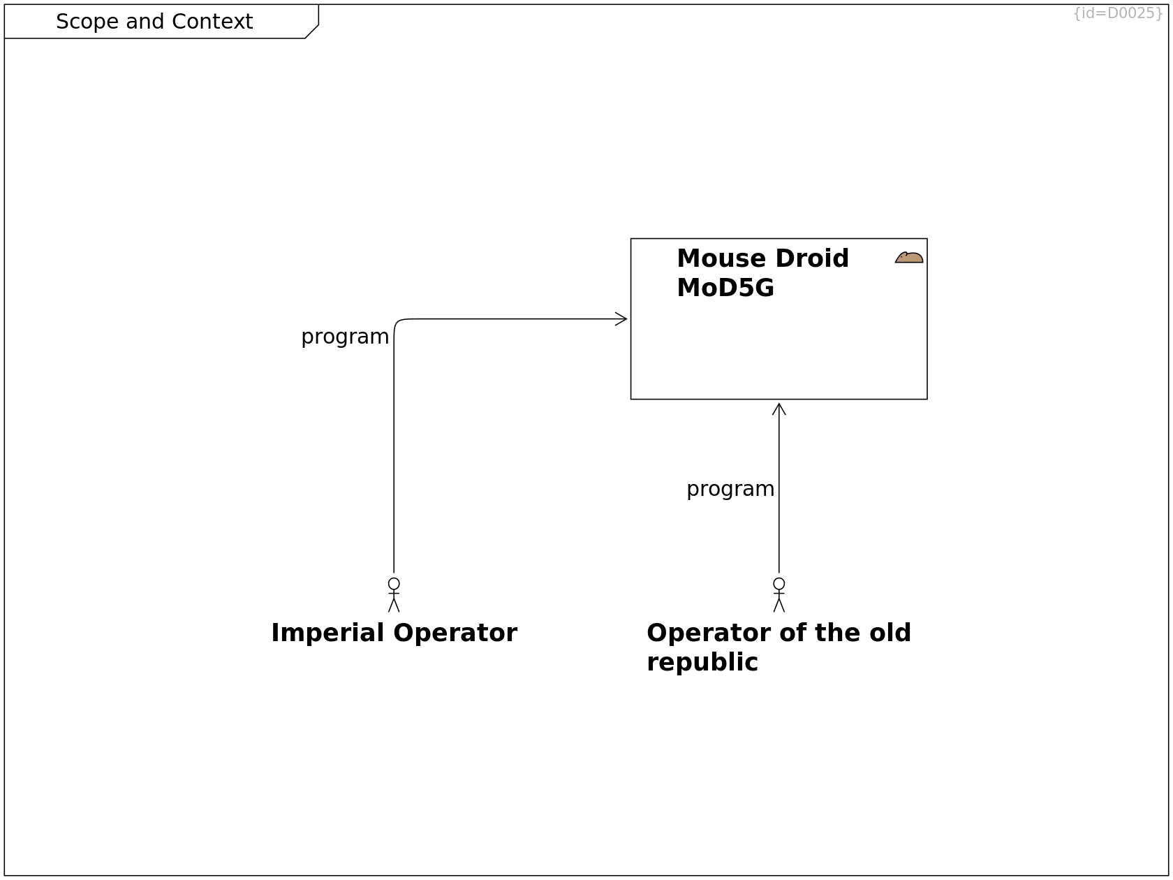
Scope and Context Component Diagram D0025
This section shows the organizational contexts of development and operational environments. (Problem Space, Software Level)
Scope and Context
Imperial Operator Actor C0082
program --> Mouse Droid MoD5G Association R0113
--|> Operator Generalization R0389
Scope and Context
Operator of the old republic Actor C0083
program --> Mouse Droid MoD5G Association R0112
--|> Operator Generalization R0388
Scope and Context, Use Cases and Requirements, Factory Context, Requirements and Goals, Operational Context, Scope and Context, Deployment View
Mouse Droid MoD5G mouse-droid Subsystem C0004
The Mouse Droid (MoD5G) is a repair droid that can be instructed to perform a mission and which then autonomously selects tactics to achieve the mission goals.
charge connector Port F0074
Via the charge connector, the energy call can be refreshed.
program connector Port F0075
Via the program connector, an operator provides the data for a mission to be performed.
Use Cases and Requirements, Operational Context, Scope and Context
Operator Actor C0216
Solution Strategy
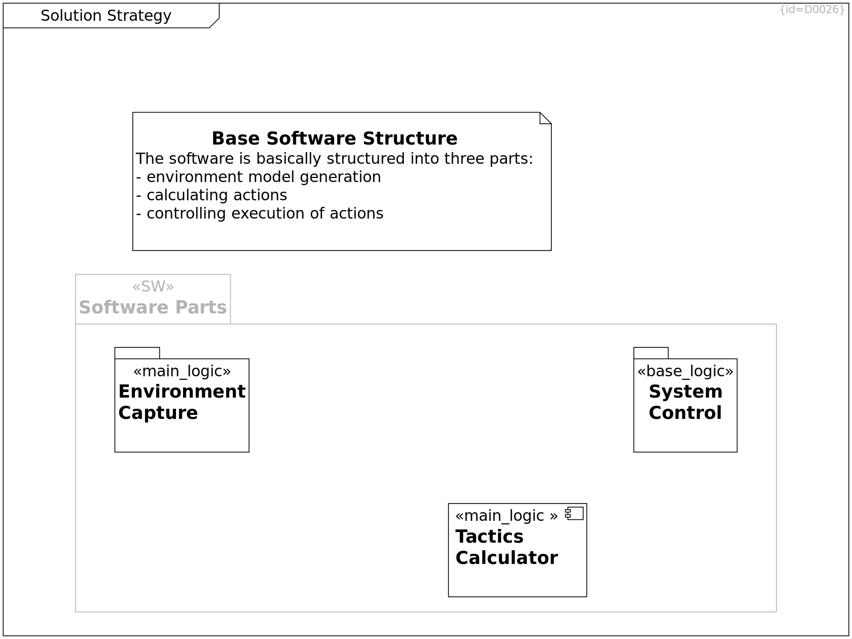
Solution Strategy Component Diagram D0026
This section shows the most fundamental principles of the software design. (Solution Space, Software Level)
Environment Capture, Solution Strategy, Building Block View, Deployment View
Environment Capture main_logic Package C0118
Environment Model Composer Sequence, Solution Strategy, Building Block View, Deployment View, Risks and Technical Debts
Tactics Calculator main_logic Component C0108
Calculate tactics based on given strategy and current situation model
System Control, Solution Strategy, Physical View, Building Block View, Deployment View
Base System Control base_logic Package C0119
Solution Strategy
Base Software Structure Comment C0121
The software is basically structured into three parts:
- environment model generation
- calculating actions
- controlling execution of actions
Solution Strategy, Physical View, Building Block View
Main Logic Software SW Package C0020
The software consists of control logic, initial data that was integrated at the factory and learned data that is aggregated during operation.
These software items are split over two logical boards and subdivided into independent execution partitions.
+-- Tactics Calculator Containment R0236
+-- Environment Capture Containment R0241
Building Block View
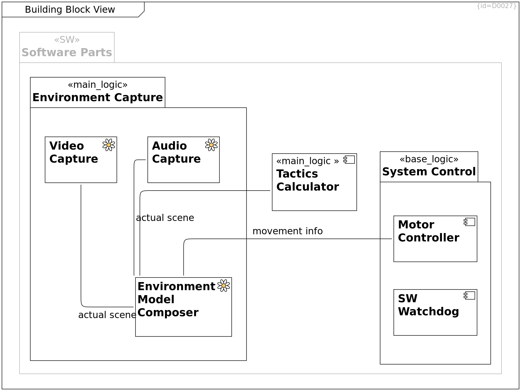
Building Block View Component Diagram D0027
This section shows the parts of the MoD5G software (Solution Space, Software Level)
Environment Capture, Environment Model Composer Sequence, Building Block View, Deployment View
Video Capture env-perception Component C0106
actual scene -- Environment Model Composer Communication Path R0155
Environment Capture, Environment Model Composer Sequence, Building Block View, Deployment View
Audio Capture env-perception Component C0107
actual scene -- Environment Model Composer Communication Path R0154
Environment Model Composer Sequence, Solution Strategy, Building Block View, Deployment View, Risks and Technical Debts
Tactics Calculator main_logic Component C0108
Calculate tactics based on given strategy and current situation model
movement info -- Motor Controller Communication Path R0347
Environment Model Composer Sequence, System Control, Building Block View, Deployment View
Motor Controller Component C0109
Move motors according to calculated tactics
Environment Capture, Solution Strategy, Building Block View, Deployment View
Environment Capture main_logic Package C0118
+-- Environment Model Composer Containment R0152
+-- Video Capture Containment R0148
+-- Audio Capture Containment R0149
System Control, Solution Strategy, Physical View, Building Block View, Deployment View
Base System Control base_logic Package C0119
+-- SW Watchdog Containment R0174
+-- Motor Controller Containment R0151
Environment Capture, Environment Model Composer Sequence, Building Block View, Deployment View
Environment Model Composer env-perception Component C0120
-- Tactics Calculator Communication Path R0156
System Control, Building Block View, Crosscutting Concepts
SW Watchdog Component C0129
The SW Watchdog shall check
- validity of data as well as
- validity of sequence of checkpoints
received from software components
on the Main Logic Board.
See also Crosscutting Concepts.
Solution Strategy, Physical View, Building Block View
Main Logic Software SW Package C0020
The software consists of control logic, initial data that was integrated at the factory and learned data that is aggregated during operation.
These software items are split over two logical boards and subdivided into independent execution partitions.
+-- Tactics Calculator Containment R0236
+-- Environment Capture Containment R0241
Environment Capture
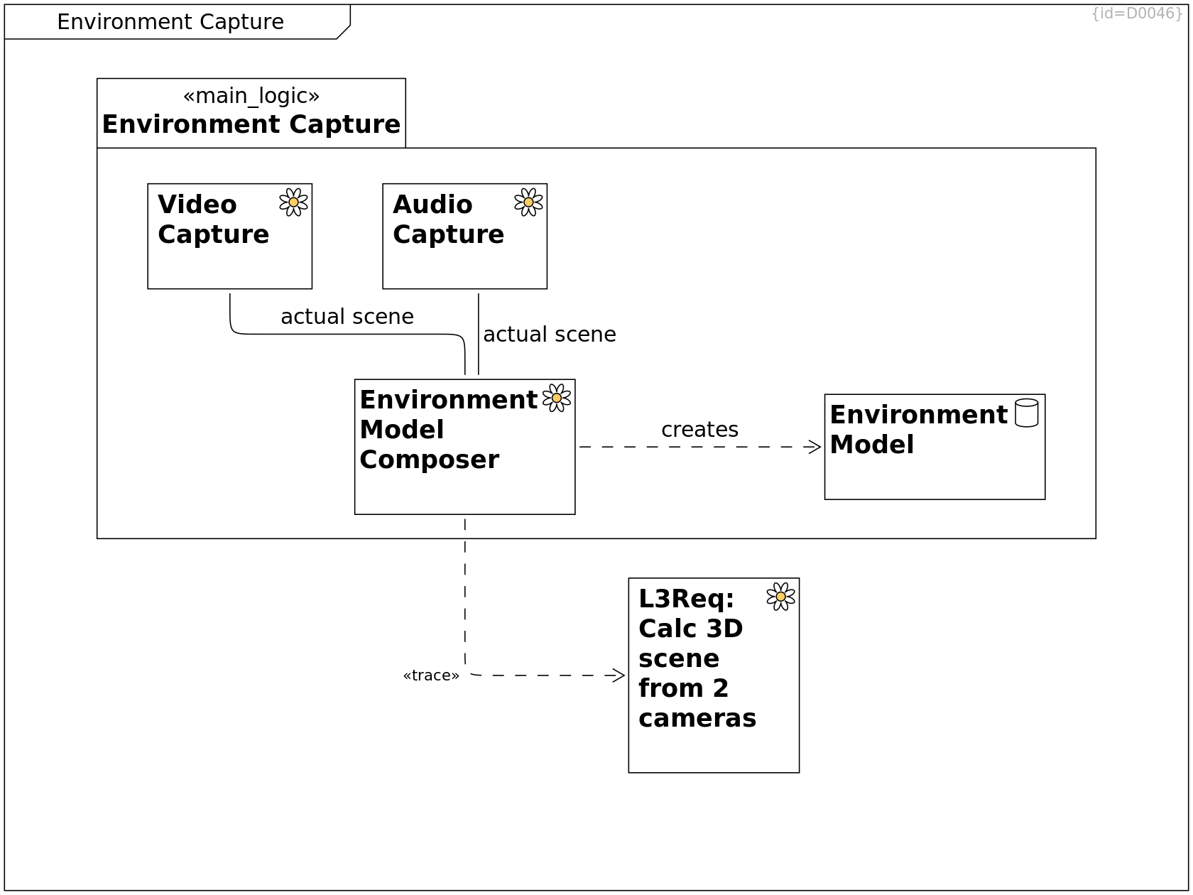
Environment Capture Component Diagram D0046
This diagram shows the software components that perceive the the outer environment and create a model from this data.
Requirements, Environment Capture
SW-Req: Calc 3D scene from 2 cameras env-perception Requirement C0151
The Main Logic Board shall create a 3D model of the environment based on 2 camera images.
Environment Capture, Environment Model Composer Sequence, Building Block View, Deployment View
Audio Capture env-perception Component C0107
actual scene -- Environment Model Composer Communication Path R0154
Environment Capture, Solution Strategy, Building Block View, Deployment View
Environment Capture main_logic Package C0118
+-- Environment Model Composer Containment R0152
+-- Video Capture Containment R0148
+-- Audio Capture Containment R0149
+-- Environment Model Containment R0261
Environment Capture, Environment Model Composer Sequence, Building Block View, Deployment View
Video Capture env-perception Component C0106
actual scene -- Environment Model Composer Communication Path R0155
Environment Capture, Environment Model Composer Sequence, Building Block View, Deployment View
Environment Model Composer env-perception Component C0120
··> SW-Req: Calc 3D scene from 2 cameras Trace R0254
creates ··> Environment Model Dependency R0260
Environment Capture, Glossary
Environment Model data Class C0111
The enironment model refers to the (limited) knowledge of the software on the real environment.
System Control
System Control Component Diagram D0047
This diagram shows the software components that perceive MoD5G internal sensor data and steer the actuators of the MoD5G.
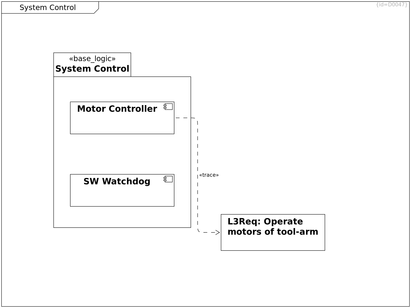
Requirements, System Control
SW-Req: Operate motors of tool-arm Requirement C0152
The Base Logic Board shall steer the motors of the tool-arm to a given 3D position.
System Control, Solution Strategy, Physical View, Building Block View, Deployment View
Base System Control base_logic Package C0119
+-- SW Watchdog Containment R0174
+-- Motor Controller Containment R0151
Environment Model Composer Sequence, System Control, Building Block View, Deployment View
Motor Controller Component C0109
Move motors according to calculated tactics
··> SW-Req: Operate motors of tool-arm Trace R0253
System Control, Building Block View, Crosscutting Concepts
SW Watchdog Component C0129
The SW Watchdog shall check
- validity of data as well as
- validity of sequence of checkpoints
received from software components
on the Main Logic Board.
See also Crosscutting Concepts.
Runtime View
Runtime View Activity Diagram D0028
This section shows the dynamic behavior of the software (Solution Space, Software Level)
This diagram shows the software states embedded in the system states. See Power States.
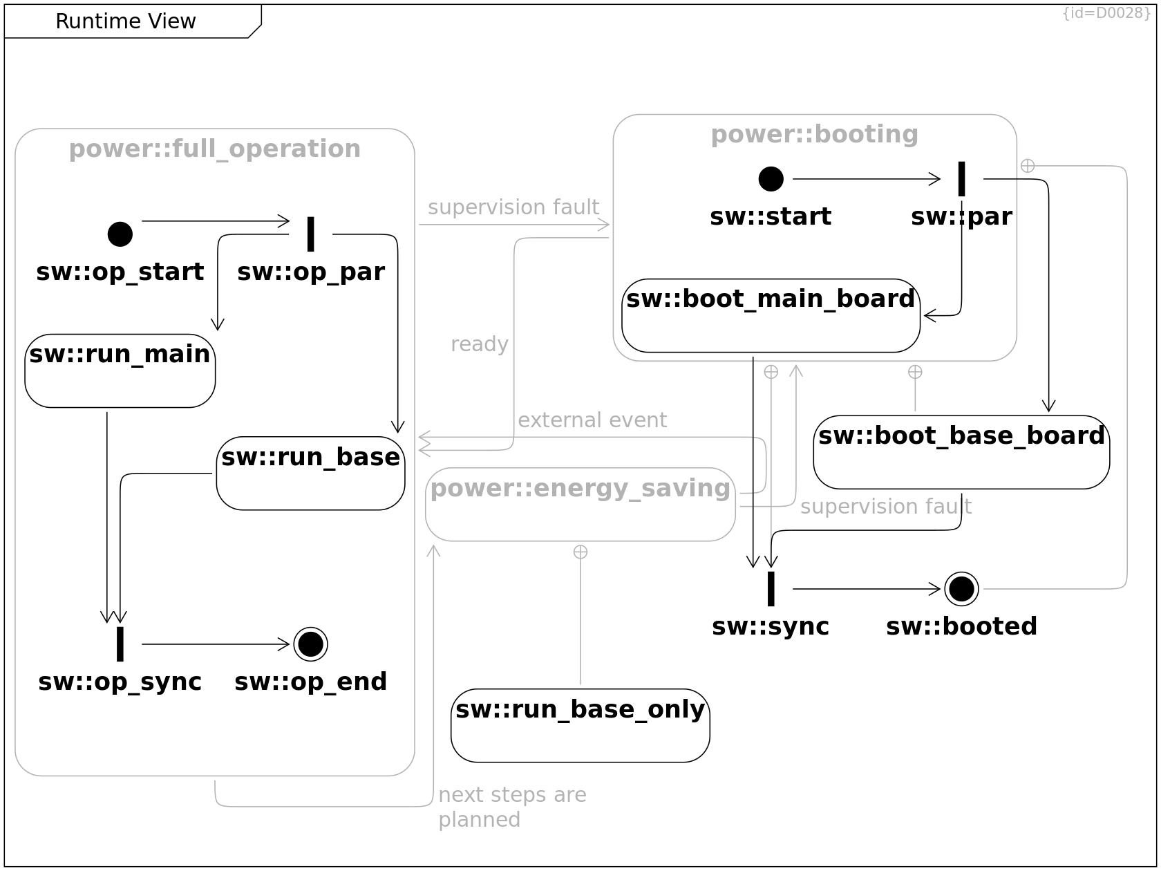
Power States, Power State Timings, Runtime View
power::booting Activity C0024
While the MoD5G is in booting state, the MoD5G can not yet react on input data; input signals from sensors are queued for later processing.
+-- sw::sync Containment R0107
+-- sw::start Containment R0099
+-- sw::par Containment R0100
+-- sw::boot_main_board Containment R0098
+-- sw::booted Containment R0110
+-- sw::boot_base_board Containment R0097
ready --> power::full_operation Control Flow R0016
Power States, Power State Timings, Runtime View
power::full_operation Activity C0025
While the MoD5G is in full_operation state, all software parts are running and able to react on input data.
+-- sw::op_sync Containment R0117
+-- sw::op_end Containment R0115
+-- sw::op_par Containment R0116
+-- sw::op_start Containment R0114
+-- sw::run_base Containment R0105
+-- sw::run_main Containment R0104
next steps are planned --> power::energy_saving Control Flow R0017
mission tactics are planned, no need to adapt
supervision fault --> power::booting Control Flow R0033
Power States, Power State Timings, Runtime View
power::energy_saving Activity C0026
While the MoD5G is in energy saving state, the MoD5G does not react on input data. Only few wakeup mechanisms can caus a transition to full operation.
+-- sw::run_base_only Containment R0106
external event --> power::full_operation Control Flow R0018
external event causes re-evaluating tactics
supervision fault --> power::booting Control Flow R0032
Runtime View
sw::boot_base_board Activity C0072
The software on the base board is initializing, not yet fully functional.
--> sw::sync Control Flow R0109
Runtime View
sw::boot_main_board Activity C0073
The software on the main board is initializing, not yet fully functional.
--> sw::sync Control Flow R0108
Runtime View
sw::start Initial Node C0074
--> sw::par Control Flow R0101
Runtime View
sw::par Fork C0075
--> sw::boot_main_board Control Flow R0102
--> sw::boot_base_board Control Flow R0103
Runtime View
sw::run_main Activity C0076
The software on the main board is initialized and running.
--> sw::op_sync Control Flow R0123
Runtime View
sw::run_base Activity C0077
The software on the base board is initialized and running.
--> sw::op_sync Control Flow R0122
Runtime View
sw::run_base_only Activity C0078
The software on the base board is initialized and running.
Runtime View
sw::sync Join C0079
--> sw::booted Control Flow R0111
Runtime View
sw::booted Final Node C0080
Runtime View
sw::op_start Initial Node C0084
--> sw::op_par Control Flow R0119
Runtime View
sw::op_end Final Node C0085
Runtime View
sw::op_par Fork C0086
--> sw::run_main Control Flow R0120
--> sw::run_base Control Flow R0121
Runtime View
sw::op_sync Join C0087
--> sw::op_end Control Flow R0118
Environment Model Composer Sequence
Environment Model Composer Sequence Sequence Diagram D0037
This diagram shows the typical communication sequence to compose the environment model.
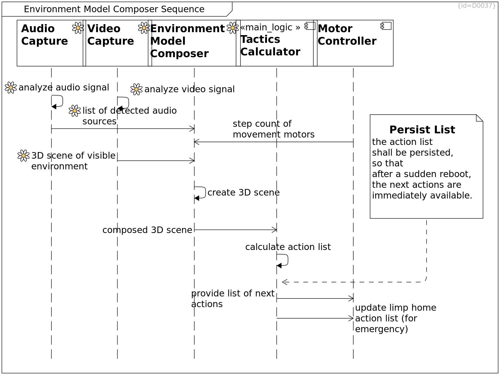
Environment Model Composer Sequence, System Control, Building Block View, Deployment View
Motor Controller Component C0109
Move motors according to calculated tactics
step count of movement motors --> Environment Model Composer Asynchronous Call R0166
step count of steering and movement motors
Environment Model Composer Sequence, Solution Strategy, Building Block View, Deployment View, Risks and Technical Debts
Tactics Calculator main_logic Component C0108
Calculate tactics based on given strategy and current situation model
calculate action list -->> Tactics Calculator Synchronous Call R0172
calculate action list to follow the given strategy
provide list of next actions --> Motor Controller Asynchronous Call R0167
update limp home action list (for emergency) --> Motor Controller Asynchronous Call R0168
For the emergency case, update the limp home action list
Environment Capture, Environment Model Composer Sequence, Building Block View, Deployment View
Environment Model Composer env-perception Component C0120
create 3D scene -->> Environment Model Composer Synchronous Call R0171
create 3D scene based on sensors, status and history.
composed 3D scene --> Tactics Calculator Asynchronous Call R0165
··>> Environment Model Composer Return R0422
Environment Capture, Environment Model Composer Sequence, Building Block View, Deployment View
Audio Capture env-perception Component C0107
analyze audio signal env-perception -->> Audio Capture Synchronous Call R0169
list of detected noise sources env-perception --> Environment Model Composer Asynchronous Call R0164
··>> Audio Capture Return R0420
Environment Capture, Environment Model Composer Sequence, Building Block View, Deployment View
Video Capture env-perception Component C0106
analyze video signal env-perception -->> Video Capture Synchronous Call R0170
3D scene of visible environment env-perception --> Environment Model Composer Asynchronous Call R0163
··>> Video Capture Return R0421
Environment Model Composer Sequence
Persist List Comment C0142
the action list
shall be persisted,
so that
after a sudden reboot,
the next actions are
immediately available.
··> Tactics Calculator Dependency R0220
Deployment View
Deployment View Deployment Diagram D0029
This section shows the deployment of the solution into the environment. (Solution Space, Software Level)
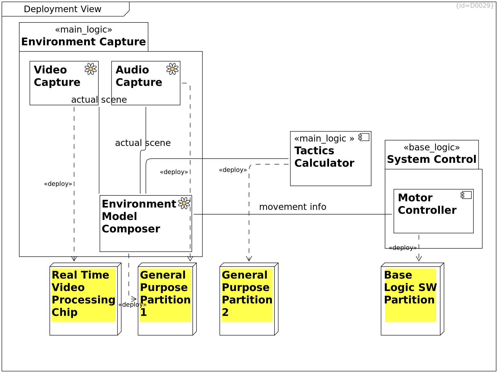
Environment Model Composer Sequence, System Control, Building Block View, Deployment View
Motor Controller Component C0109
Move motors according to calculated tactics
··> Base Logic SW Partition Deployment R0200
Deployment View, Software [subsystem]
Base Logic SW Partition Node C0064
Deployment View, Software [subsystem]
General Purpose Partition 2 Node C0063
Environment Model Composer Sequence, Solution Strategy, Building Block View, Deployment View, Risks and Technical Debts
Tactics Calculator main_logic Component C0108
Calculate tactics based on given strategy and current situation model
··> General Purpose Partition 2 Deployment R0202
movement info -- Motor Controller Communication Path R0347
Environment Capture, Environment Model Composer Sequence, Building Block View, Deployment View
Audio Capture env-perception Component C0107
actual scene -- Environment Model Composer Communication Path R0154
··> General Purpose Partition 1 Deployment R0204
Deployment View, Software [subsystem]
General Purpose Partition 1 Node C0062
Deployment View, Software [subsystem]
Real Time Video Processing Chip Node C0060
Environment Capture, Environment Model Composer Sequence, Building Block View, Deployment View
Video Capture env-perception Component C0106
actual scene -- Environment Model Composer Communication Path R0155
··> Real Time Video Processing Chip Deployment R0201
Environment Capture, Environment Model Composer Sequence, Building Block View, Deployment View
Environment Model Composer env-perception Component C0120
-- Tactics Calculator Communication Path R0156
··> General Purpose Partition 1 Deployment R0203
Environment Capture, Solution Strategy, Building Block View, Deployment View
Environment Capture main_logic Package C0118
+-- Environment Model Composer Containment R0152
+-- Video Capture Containment R0148
+-- Audio Capture Containment R0149
System Control, Solution Strategy, Physical View, Building Block View, Deployment View
Base System Control base_logic Package C0119
+-- Motor Controller Containment R0151
Crosscutting Concepts
Crosscutting Concepts Component Diagram D0030
This section shows the recurring concepts within the the designed solution. (Solution Space, Software Level)
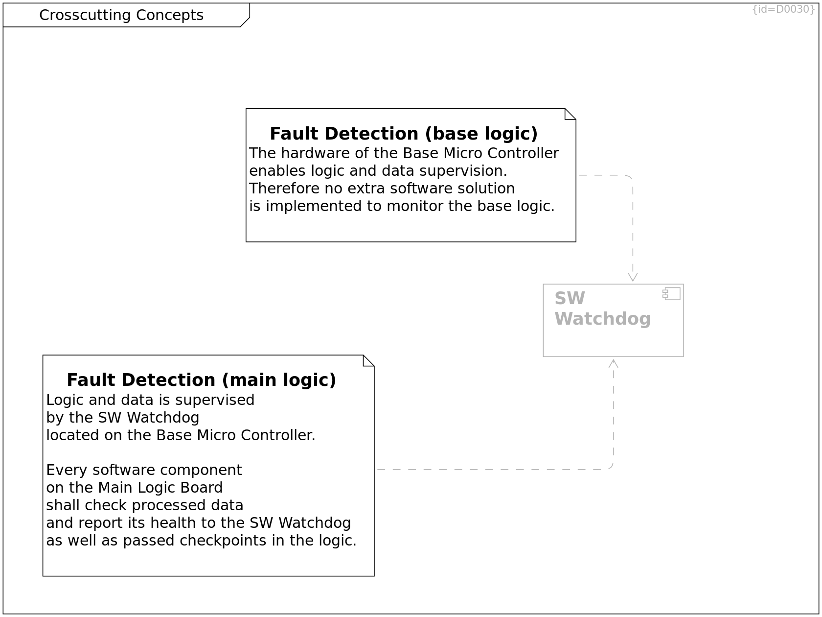
Crosscutting Concepts, Risks and Technical Debts
Fault Detection (main logic) Comment C0127
Logic and data is supervised
by the SW Watchdog
located on the Base Micro Controller.
Every software component
on the Main Logic Board
shall check processed data
and report its health to the SW Watchdog
as well as passed checkpoints in the logic.
see Architecture Decisions
··> SW Watchdog Dependency R0175
Crosscutting Concepts
Fault Detection (base logic) Comment C0128
The hardware of the Base Micro Controller
enables logic and data supervision.
Therefore no extra software solution
is implemented to monitor the base logic.
··> SW Watchdog Dependency R0198
System Control, Building Block View, Crosscutting Concepts
SW Watchdog Component C0129
The SW Watchdog shall check
- validity of data as well as
- validity of sequence of checkpoints
received from software components
on the Main Logic Board.
See also Crosscutting Concepts.
Architecture Decisions
Architecture Decisions decision Component Diagram D0031
This section documents the major design decisions. (Solution Space, Software Level)
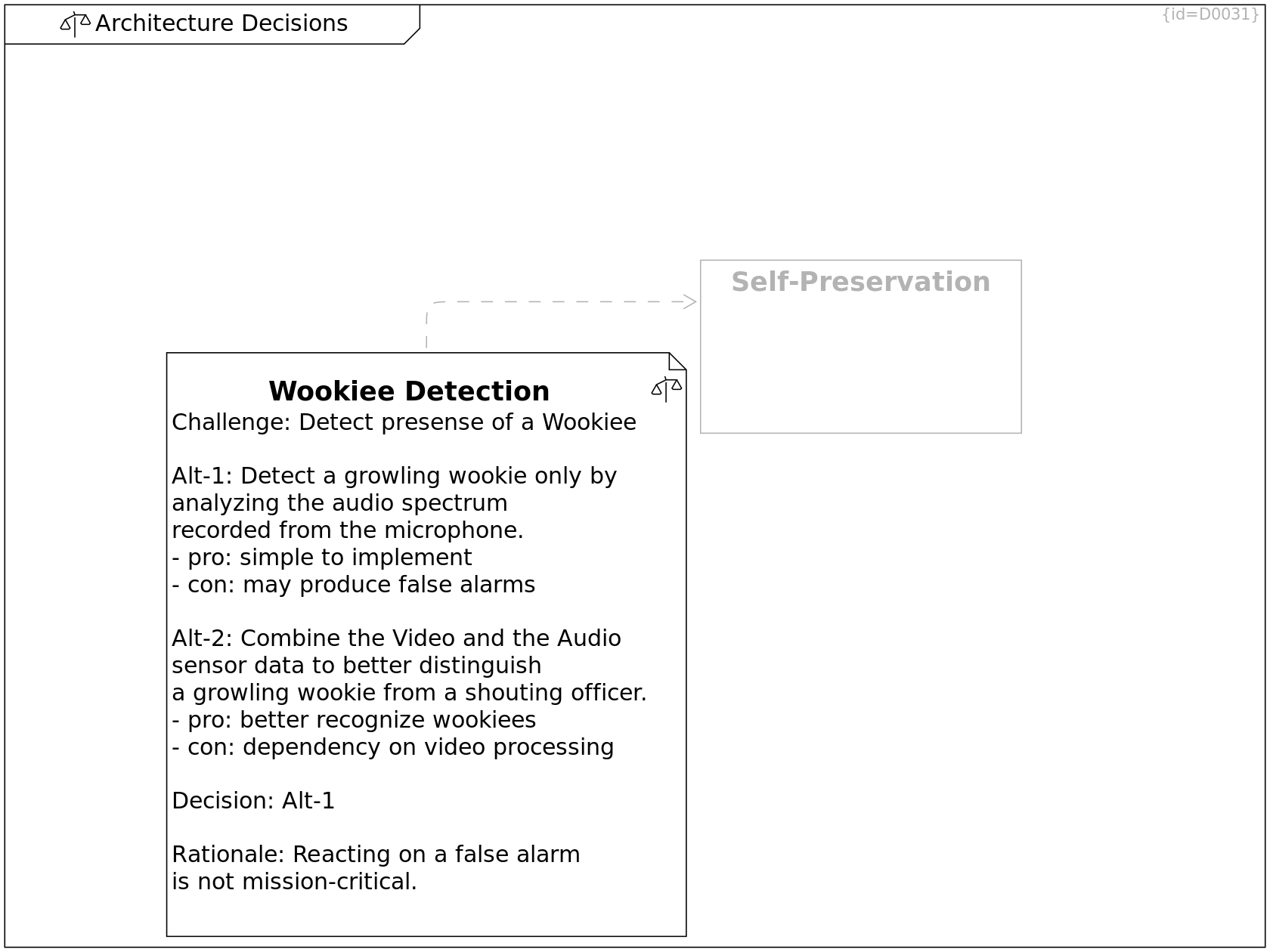
Architecture Decisions
Wookiee Detection decision Comment C0131
Challenge: Detect presense of a Wookiee
Alt-1: Detect a growling wookie only by
analyzing the audio spectrum
recorded from the microphone.
- pro: simple to implement
- con: may produce false alarms
Alt-2: Combine the Video and the Audio
sensor data to better distinguish
a growling wookie from a shouting officer.
- pro: better recognize wookiees
- con: dependency on video processing
Decision: Alt-1
Rationale: Reacting on a false alarm
is not mission-critical.
··> Self-Preservation Dependency R0177
Constraints, Architecture Decisions
Self-Preservation Requirement C0081
In case a wookiee growls at the MoD5G,
it shall flee for self-preservation
Quality Requirements
Quality Requirements Component Diagram D0032
This section shows the major quality scenarios. (Problem Space, Software Level)
Similar to Quality Requirements for system level, this section shows quality expectations: The WHAT shall be implemented, not the HOW.
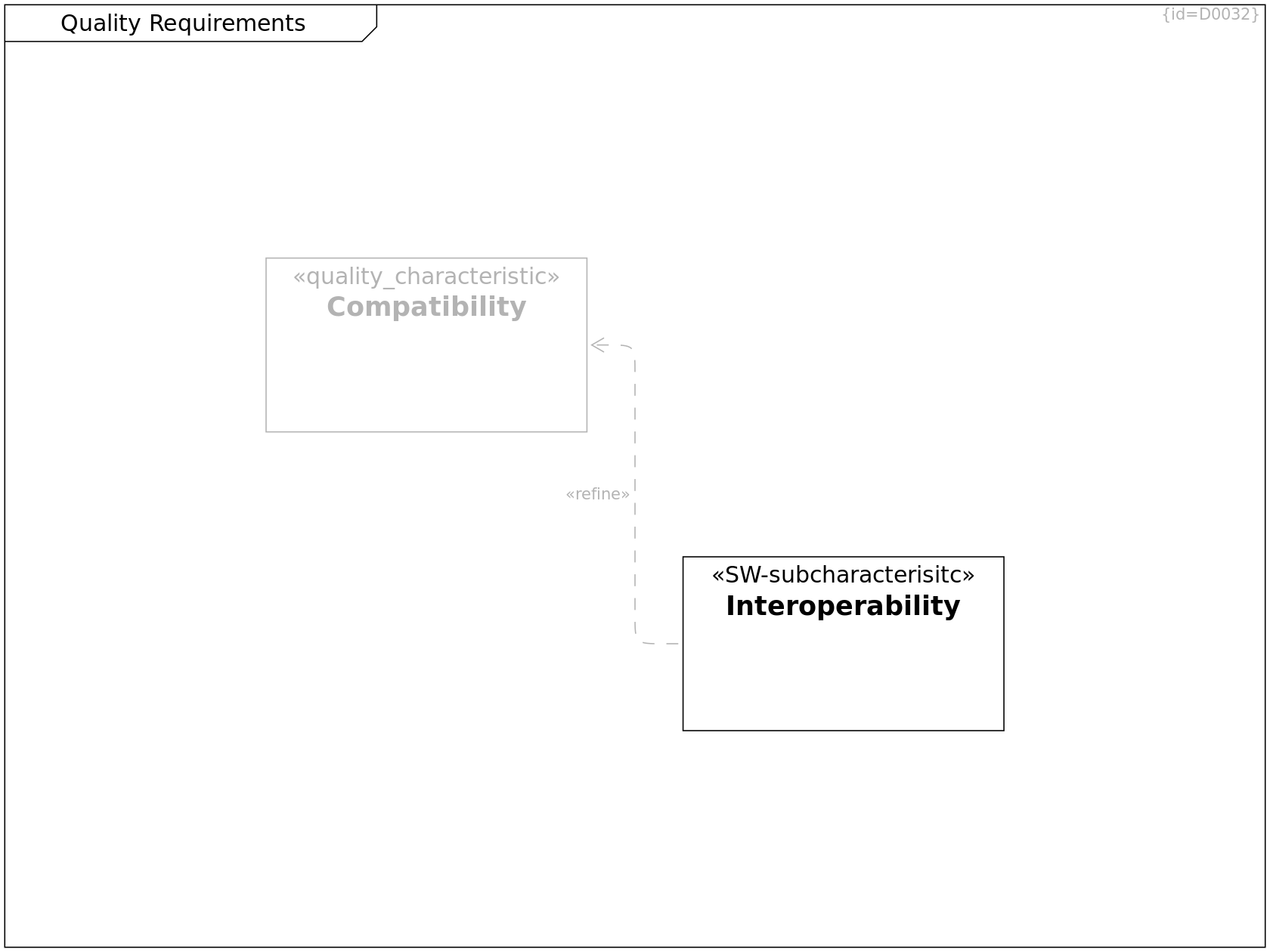
Quality Tree, Quality Requirements, Quality Requirements
Compatibility quality_characteristic Requirement C0122
Compatibility defines a set of attributes that measures how well data and messages can be exchanged with other programs and/or versions.
Quality Tree, Constraints, Quality Scenarios, Quality Requirements
Interoperability SW-subcharacterisitc Requirement C0123
The programming and charging interfaces
of the MoD5G shall be compatible to
- old republic terminals
- imperial terminals
··> Compatibility Refinement R0158
Quality Tree
Quality Tree Requirement Diagram D0043
When specifying quality requirements, these are categorized by two dimensions:
1) Which characteristic do they affect
2) Which use case do they serve
Thich diagram lists the quality requirements ordered by their main characteristic.
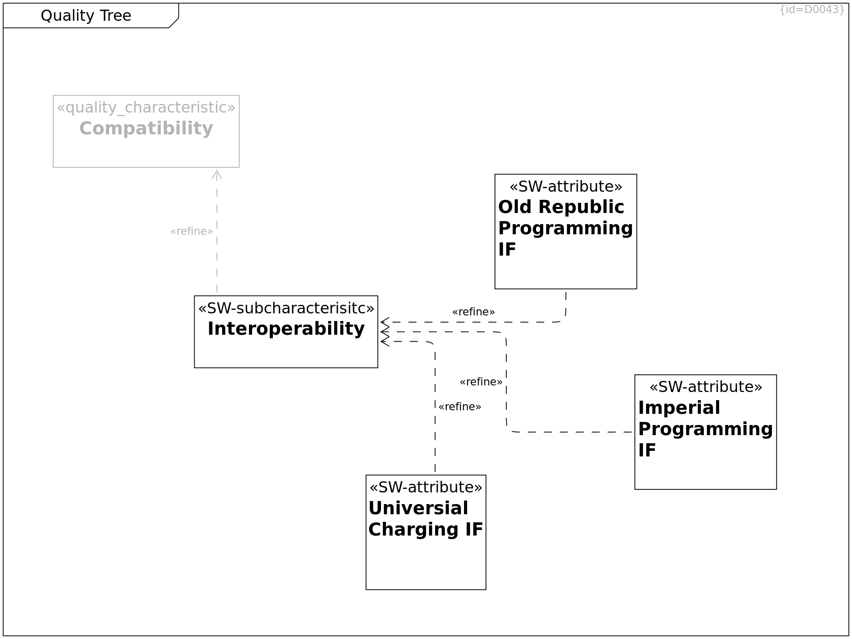
Quality Tree
Old Republic Programming IF SW-attribute Requirement C0124
The old republic protocol
for programming a droid
shall be supported.
··> Interoperability Refinement R0159
Quality Tree
Imperial Programming IF SW-attribute Requirement C0125
The imperial protocol
for programming a droid
shall be supported.
··> Interoperability Refinement R0160
Quality Tree
Universial Charging IF SW-attribute Requirement C0126
The intergalactic standard protocol for power charging
shall be supported.
··> Interoperability Refinement R0161
Quality Tree, Constraints, Quality Scenarios, Quality Requirements
Interoperability SW-subcharacterisitc Requirement C0123
The programming and charging interfaces
of the MoD5G shall be compatible to
- old republic terminals
- imperial terminals
··> Compatibility Refinement R0158
Quality Tree, Quality Requirements, Quality Requirements
Compatibility quality_characteristic Requirement C0122
Compatibility defines a set of attributes that measures how well data and messages can be exchanged with other programs and/or versions.
Quality Scenarios
Quality Scenarios Requirement Diagram D0042
When specifying quality requirements, these are categorized by two dimensions:
1) Which characteristic do they affect
2) Which use case do they serve
Thich diagram lists the use cases which have special importance for quality requirements.
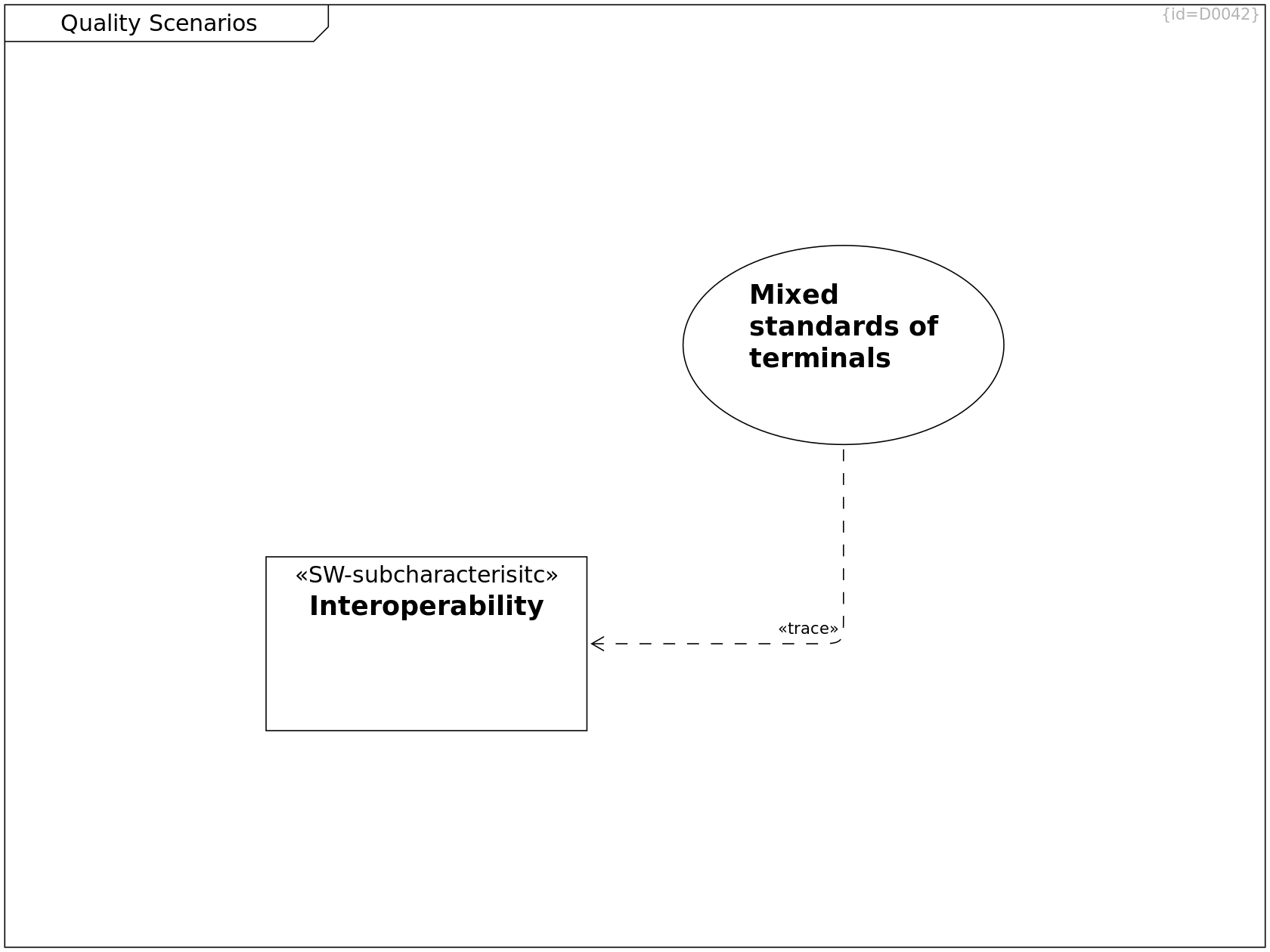
Quality Scenarios
Mixed standards of terminals Use Case C0145
precondition:
- The MoD5G operates in an environment
providing mixed terminal standards
trigger:
- The MoD5G drives to a charging or programming terminal
which complied to either old republic or imperial standard.
scenario:
- The MoD5G determines the applicable standard
- The MoD5G uses the terminal for programming or charging
··> Interoperability Trace R0227
Quality Tree, Constraints, Quality Scenarios, Quality Requirements
Interoperability SW-subcharacterisitc Requirement C0123
The programming and charging interfaces
of the MoD5G shall be compatible to
- old republic terminals
- imperial terminals
Risks and Technical Debts
Risks and Technical Debts Component Diagram D0033
This section lists the risks and not-yet-addressed requirements. (Solution Space, Software Level)
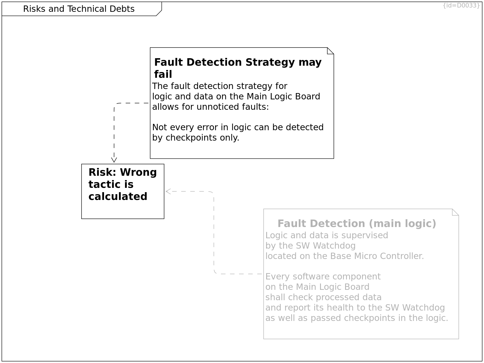
Risks and Technical Debts
Fault Detection Strategy may fail Comment C0130
The fault detection strategy for
logic and data on the Main Logic Board
allows for unnoticed faults:
Not every error in logic can be detected
by checkpoints only.
··> Wrong tactic is calculated Dependency R0181
Crosscutting Concepts, Risks and Technical Debts
Fault Detection (main logic) Comment C0127
Logic and data is supervised
by the SW Watchdog
located on the Base Micro Controller.
Every software component
on the Main Logic Board
shall check processed data
and report its health to the SW Watchdog
as well as passed checkpoints in the logic.
see Architecture Decisions
··> Wrong tactic is calculated Dependency R0341
Risks and Technical Debts
Wrong tactic is calculated Risk Requirement C0134
- cause/fault: Due to cosmic rays,
the main logic board performs a miscalculation
that goes unnoticed by control flow supervision
- risk/failure: the MoD5G calculates a tactic that
results in falling off a cliff
Failure Mode: An unsuitable tactical plan is executed Tagged Value F0067
Effect: The MoD5G does not reach the target location Tagged Value F0068
Cause: The memory was disturbed by environmental effects Tagged Value F0069
Prevent: - Tagged Value F0070
Detect: Supervise correct order of control/checkpoints Tagged Value F0071
··> Tactics Calculator Trace R0340
Environment Model Composer Sequence, Solution Strategy, Building Block View, Deployment View, Risks and Technical Debts
Tactics Calculator main_logic Component C0108
Calculate tactics based on given strategy and current situation model
Glossary
Glossary Class Diagram D0034
This section explains the used terms. (Domain and Solution Space, Software Level)
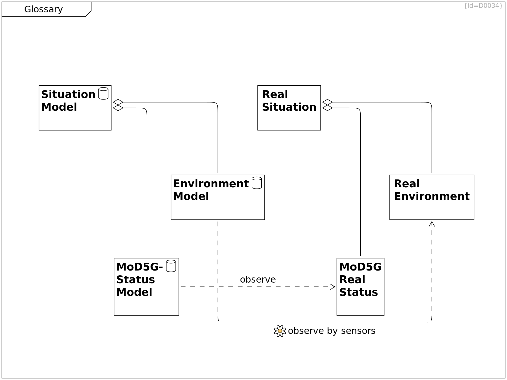
Glossary
Situation Model data Class C0110
The situation model refers to the (limited/erroneous) knowledge of the software on environment and status.
o-- MoD5G-Status Model Aggregation R0142
o-- Environment Model Aggregation R0143
Environment Capture, Glossary
Environment Model data Class C0111
The enironment model refers to the (limited) knowledge of the software on the real environment.
observe by sensors env-perception ··> Real Environment Dependency R0146
Sensor data is the basis for assuming an environment model.
Glossary
MoD5G-Status Model data Class C0112
The status model refers to the (limited) knowledge of the software on the real status.
observe ··> MoD5G Real Status Dependency R0147
Sensor data is the basis for assuming a status model. The algorithm for deriving a status model shall take into account that a sensor may be defect and/or a measured value may indicate a defect (which again may have several causes).
Glossary
Real Situation Class C0113
The real situation refers to the reality of system status and environment.
o-- MoD5G Real Status Aggregation R0144
o-- Real Environment Aggregation R0145
Glossary
Real Environment Class C0114
The real environment refers to the physical environment of the system.
Glossary
MoD5G Real Status Class C0115
The real status refers to the real system status of the MoD5G. This may differ from what the sensors report.
Runtime View
Runtime View Interation Overview Diagram D0007
This section shows the dynamic behavior of the system (Solution Space, System Level)
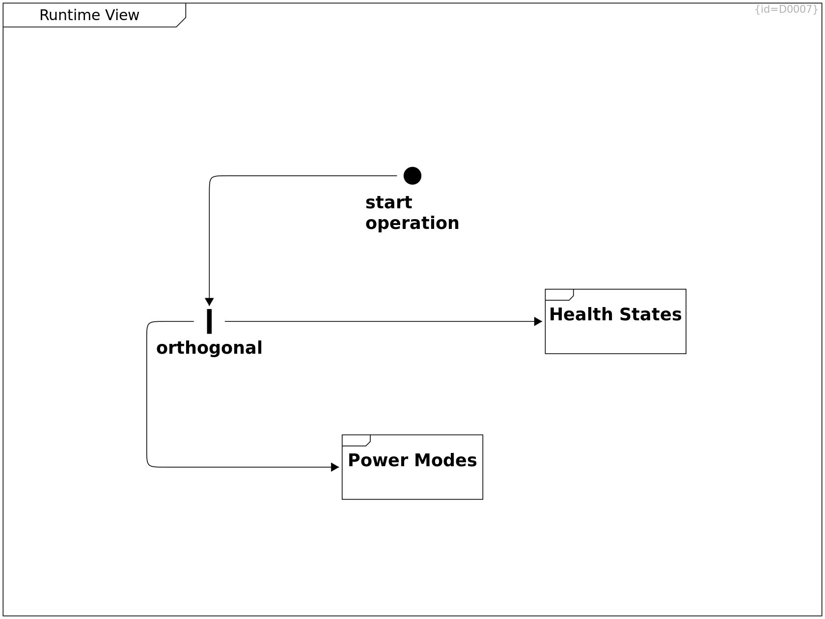
Runtime View
start operation Initial Node C0153
After production or repair, this initial state indicates the system start.
-->> orthogonal Synchronous Call R0262
Runtime View
orthogonal Fork C0154
operation mode, power states and heath states are three distinct statemachines that handle their state-transitions independantly.
-->> Health States Synchronous Call R0263
-->> Power States Synchronous Call R0264
-->> Operation Modes Synchronous Call R0303
need ··> Power States Dependency R0304
Power States
Power States Activity Diagram D0020
This diagram shows the power states that are globally valid synchronized to all parts of the system.
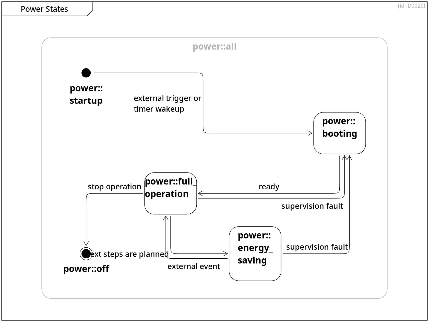
Power States, Power State Timings
power::startup Initial Node C0023
The startup pseudo-state indicates where the transitions start when powered on.
external trigger or timer wakeup --> power::booting Control Flow R0015
Power States, Power State Timings, Runtime View
power::booting Activity C0024
While the MoD5G is in booting state, the MoD5G can not yet react on input data; input signals from sensors are queued for later processing.
ready --> power::full_operation Control Flow R0016
Power States, Power State Timings, Runtime View
power::full_operation Activity C0025
While the MoD5G is in full_operation state, all software parts are running and able to react on input data.
next steps are planned --> power::energy_saving Control Flow R0017
mission tactics are planned, no need to adapt
stop operation --> power::off Control Flow R0019
stop operation, set wakeup time
supervision fault --> power::booting Control Flow R0033
Power States, Power State Timings, Runtime View
power::energy_saving Activity C0026
While the MoD5G is in energy saving state, the MoD5G does not react on input data. Only few wakeup mechanisms can caus a transition to full operation.
external event --> power::full_operation Control Flow R0018
external event causes re-evaluating tactics
supervision fault --> power::booting Control Flow R0032
Power States, Power State Timings
power::off Final Node C0027
The off pseudo-state indicates where the transition logic ends when powered off.
Power States
power::all Activity C0138
The statemachine of power states shows the triggers and transitions between states that enable or disable hardware parts.
+-- power::booting Containment R0192
+-- power::energy_saving Containment R0193
+-- power::full_operation Containment R0194
+-- power::startup Containment R0195
+-- power::off Containment R0196
Power State Timings
Power State Timings Timing Diagram D0041
This diagram shows the expected startup and shutdown timings.
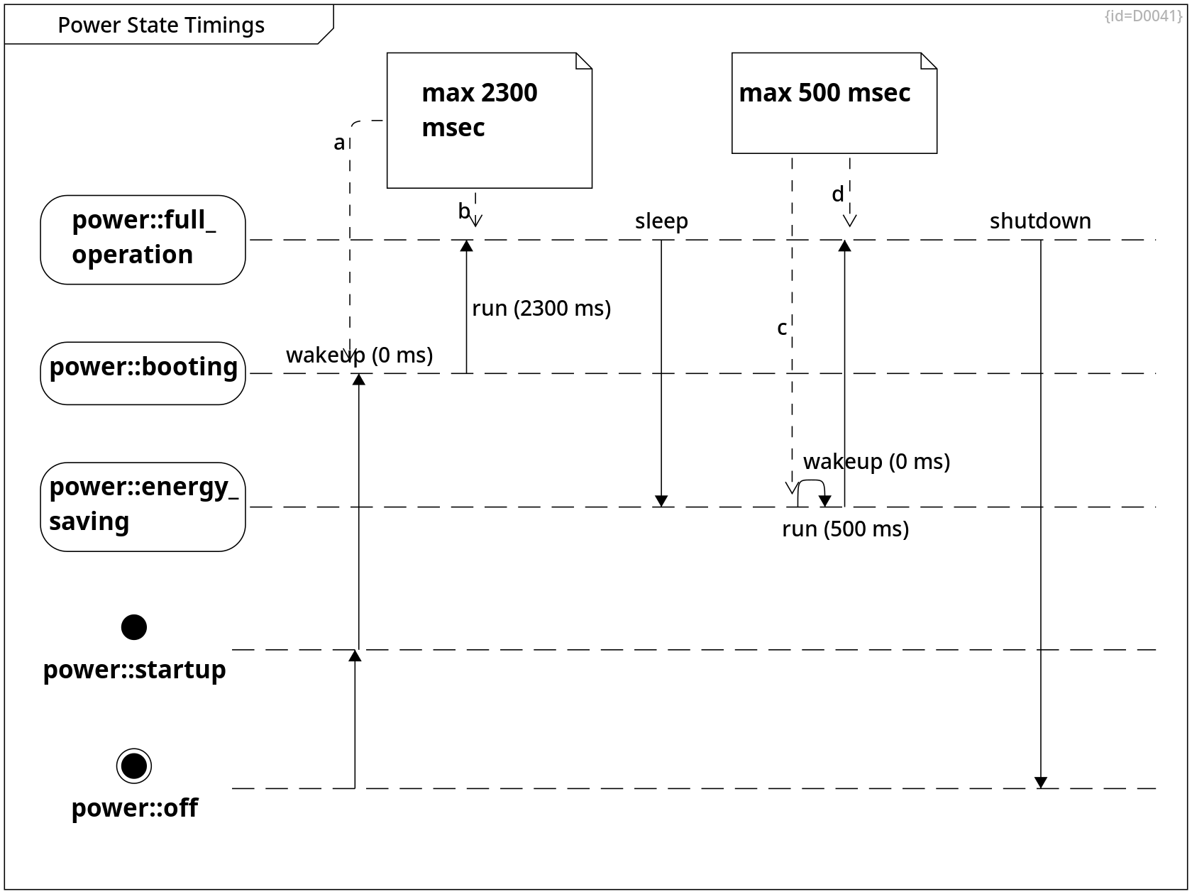
Power States, Power State Timings
power::off Final Node C0027
The off pseudo-state indicates where the transition logic ends when powered off.
-->> power::startup Synchronous Call R0209
Power States, Power State Timings, Runtime View
power::full_operation Activity C0025
While the MoD5G is in full_operation state, all software parts are running and able to react on input data.
sleep -->> power::energy_saving Synchronous Call R0212
shutdown -->> power::off Synchronous Call R0215
Power States, Power State Timings
power::startup Initial Node C0023
The startup pseudo-state indicates where the transitions start when powered on.
wakeup (0 ms) -->> power::booting Synchronous Call R0210
Power States, Power State Timings, Runtime View
power::booting Activity C0024
While the MoD5G is in booting state, the MoD5G can not yet react on input data; input signals from sensors are queued for later processing.
run (2300 ms) -->> power::full_operation Synchronous Call R0211
Power States, Power State Timings, Runtime View
power::energy_saving Activity C0026
While the MoD5G is in energy saving state, the MoD5G does not react on input data. Only few wakeup mechanisms can caus a transition to full operation.
wakeup (0 ms) -->> power::energy_saving Synchronous Call R0213
run (500 ms) -->> power::full_operation Synchronous Call R0214
Power State Timings
max 2300 msec Comment C0139
a ··> power::booting Dependency R0218
b ··> power::full_operation Dependency R0216
Power State Timings
max 500 msec Comment C0140
c ··> power::energy_saving Dependency R0219
d ··> power::full_operation Dependency R0217
Health States
Health States State Diagram D0021
This diagram shows the health states of the MoD5G system.
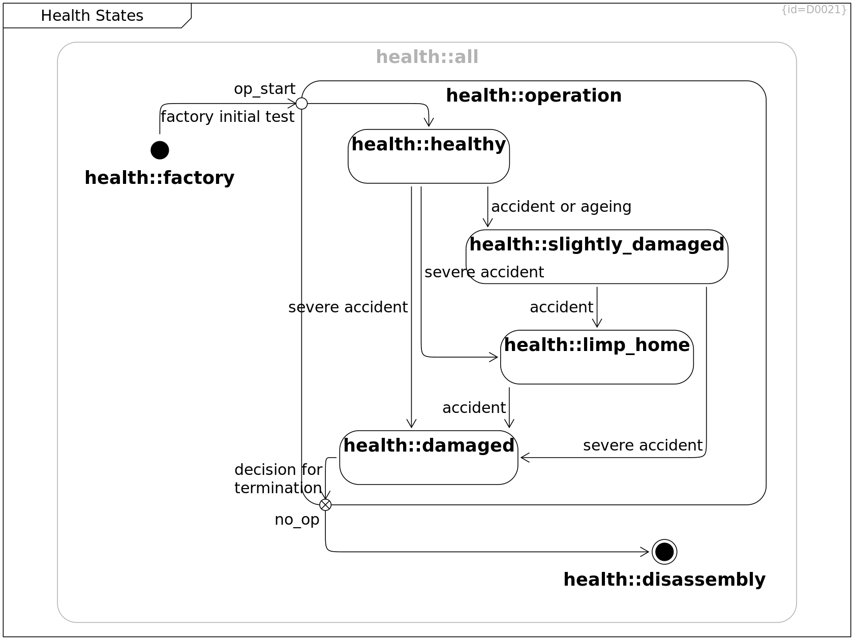
Health States
health::factory Initial Node C0028
The health state when leaving the factory.
A sound manufacturing where each step is tested for faults ensures a healthy state.
factory initial test --> health::operation Control Flow R0207
Health States
health::disposal Final Node C0029
The MoD5G is disassembled.
Health States
health::healthy State C0030
The MoD5G is healthy,
the own HW parts work as expected.
accident or ageing --> health::slightly_damaged Control Flow R0021
severe accident --> health::damaged Control Flow R0029
severe accident --> health::limp_home Control Flow R0030
Health States
health::slightly_damaged State C0031
The MoD5G is not fully healthy anymore,
some of the own HW parts may not work as expected.
These impediments are minor, the functionality of the MoD5G is not severely impacted.
accident --> health::limp_home Control Flow R0022
severe accident --> health::damaged Control Flow R0031
Failure Modes of Energy Cell, Failure Modes of Base Logic Board, Health States, Risks, Failure Modes of Motors and Wheels
health::limp_home State C0032
The MoD5G is not fully healthy anymore,
some of the own HW parts may not work as expected.
In this case where the full operation is not possible anymore, the MoD5G shall drive back to the home charging station.
accident --> health::damaged Control Flow R0023
Health States
health::damaged State C0033
The MoD5G is not healthy anymore,
relevant own HW parts do not work as expected.
decision for termination --> health::operation Control Flow R0206
Health States
health::operation State C0034
The MoD5G is being operated, the health state is monitored.
op_start Entry F0019
When finishing the manufacturing process, a final test demonstrates full functionality.
After that, the MoD5G is ready to be operated.
no_op Exit F0018
The MoD5Gis taken out of service.
+-- health::limp_home Containment R0024
+-- health::slightly_damaged Containment R0025
+-- health::healthy Containment R0026
+-- health::damaged Containment R0027
--> health::disposal Control Flow R0205
--> health::healthy Control Flow R0208
Health States
health::all State C0137
The statemachine of all health states
+-- health::factory Containment R0189
+-- health::operation Containment R0190
+-- health::disposal Containment R0191
Deployment View
Deployment View Deployment Diagram D0008
This section shows the deployment of the solution into the environment. (Solution Space, System Level)
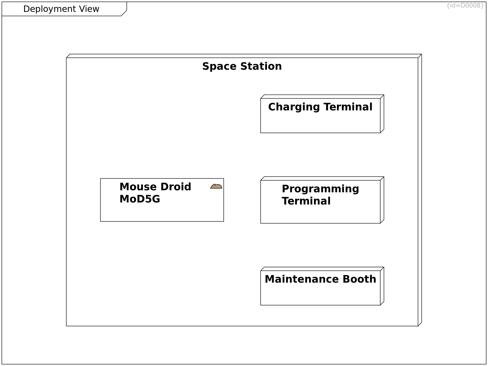
Deployment View
Space Station Node C0095
A station allows persons and goods to arrive, stay, leave or transit.
This station is engineered for that purpose; it is not attached to a natural asteroid or planet.
+-- Programming Terminal Containment R0129
+-- Charging Terminal Containment R0130
+-- Maintenance Booth Containment R0131
+-- Mouse Droid MoD5G Containment R0128
Scope and Context, Use Cases and Requirements, Factory Context, Requirements and Goals, Operational Context, Scope and Context, Deployment View
Mouse Droid MoD5G mouse-droid Subsystem C0004
The Mouse Droid (MoD5G) is a repair droid that can be instructed to perform a mission and which then autonomously selects tactics to achieve the mission goals.
charge connector Port F0074
Via the charge connector, the energy call can be refreshed.
program connector Port F0075
Via the program connector, an operator provides the data for a mission to be performed.
retrieve mission --> Programming Terminal Association R0378
The MoD5G connects to a terminal in order to retrieve the next mission to be performed.
charge --> Charging Terminal Association R0379
The MoD5G connects to a terminal in order to charge its energy cell.
Operational Context, Deployment View
Programming Terminal Node C0096
This terminal programs the next mission for the MoD5G.
program connector Port F0073
Via the program connector, an operator instructs the MoD5G on the mission to be performed.
Operational Context, Deployment View
Charging Terminal Node C0097
This terminal charges the energy cell of the MoD5G.
charge connector Port F0072
Via the charge connector, the energy call of the MoD5G or other droids can be refreshed.
Operational Context, Deployment View
Maintenance Booth Node C0098
At this booth, a mechanic analyzes the health of the MoD5G and replaces parts if damaged.
Crosscutting Concepts
Crosscutting Concepts Class Diagram D0009
This section shows the recurring concepts within the the designed solution. (Solution Space, System Level)
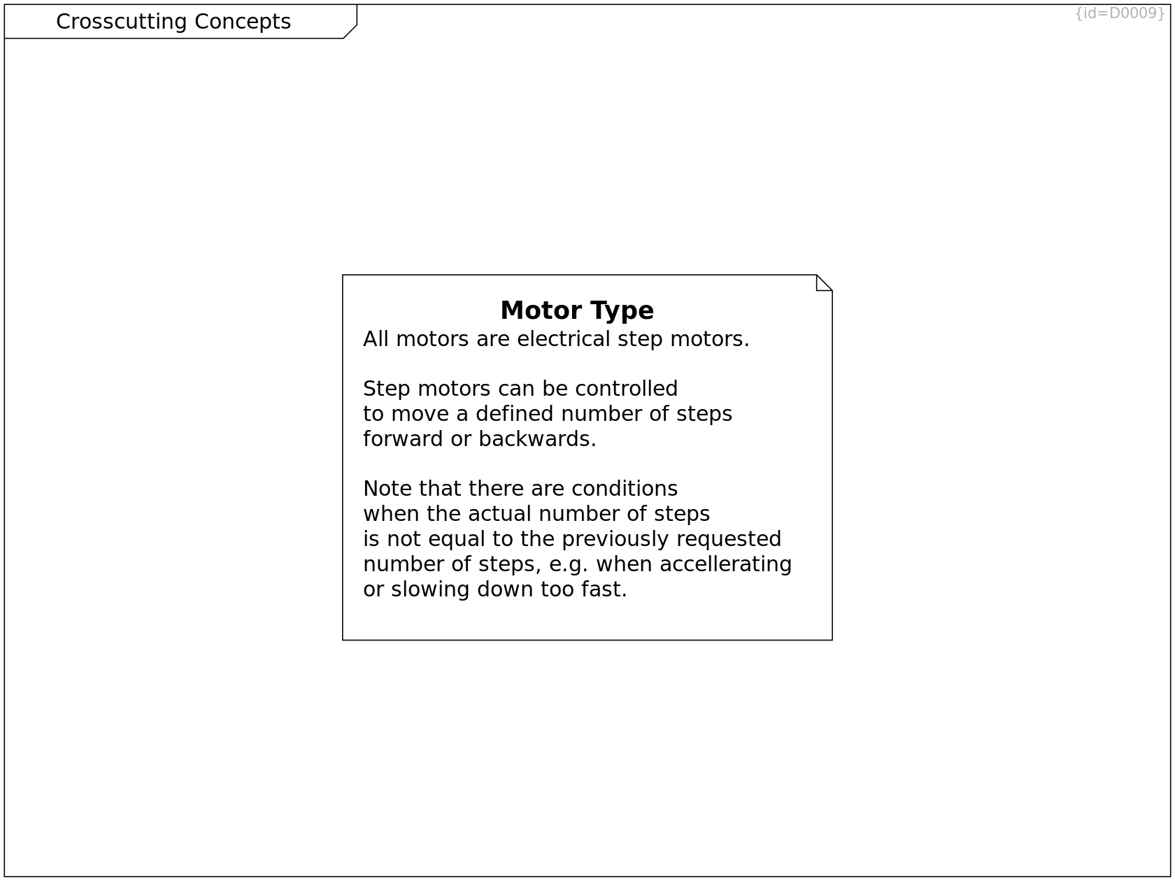
Crosscutting Concepts
Motor Type Comment C0099
Step motors can be controlled
to move a defined number of steps
forward or backwards.
··> Step Motor Dependency R0395
Crosscutting Concepts, Electric Parts and Electronics
Step Motor Comment C0218
All motors are electrical step motors.
Crosscutting Concepts
Caveat of Step Motor Comment C0219
Note that there are conditions
when the actual number of moved steps
is not equal to the previously requested
number of steps, e.g. when accellerating
or slowing down too fast.
To prevent this,
either implement smooth start and stop phases
or read-back the actual number of steps taken.
··> Step Motor Dependency R0394
Architecture Decisions
Architecture Decisions decision Component Diagram D0010
This section documents the major design decisions. (Solution Space, System Level)
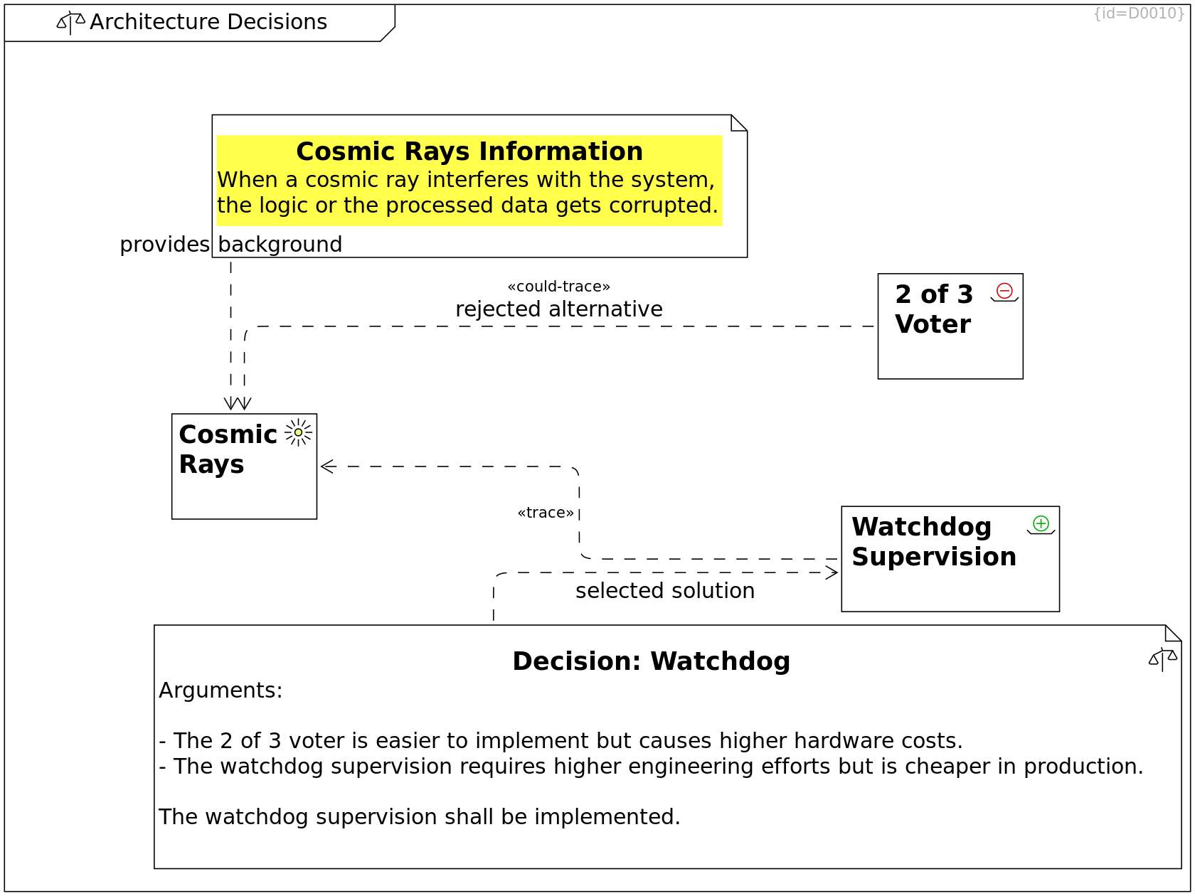
Constraints, Architecture Decisions
Cosmic Rays environment Requirement C0002
The droid shall ensure data and program integrity.
It shall continue operation after cosmic rays have interfered with data storage or program execution.
Corrupted data must not be stored permanently.
Architecture Decisions
2 of 3 Voter rejected_alternative Requirement C0100
In order to support integrity of the system, the logic boards and the data storages are deployed three times as three identical parts.
All three parts shall produce the same outcomes given the same input.
If one deviates, it's result is ignored and the part is rebooted.
rejected alternative could-trace ··> Cosmic Rays Trace R0135
Architecture Decisions
Cosmic Rays Information Comment C0101
When a cosmic ray interferes with the system,
the logic or the processed data gets corrupted.
refine the challenge to solve ··> Cosmic Rays Dependency R0132
Architecture Decisions
Watchdog Supervision chosen_alternative Requirement C0102
In order to support integrity of the logic and data,
a multi-stage hierarchy supervision shall be implemented.
Software watchdogs shall supervise the running software parts
in a way that logic errors and corrupted data can be detected.
A hardware watchdog shall supervise the software watchdogs.
In case of a failure in the supervised logic/data, the system shall reboot.
In case of a failure in the monitors, the system may reboot
or it shall fall back to a valid supervision mode.
··> Cosmic Rays Trace R0134
Architecture Decisions
Decision: Watchdog decision Comment C0103
Arguments:
- The 2 of 3 voter is easier to implement but causes higher hardware costs.
- The watchdog supervision requires higher engineering efforts but is cheaper in production.
The watchdog supervision shall be implemented.
selected solution ··> Watchdog Supervision Dependency R0133
Risks
Risks Use Case Diagram D0062
This section lists the technical risks that shall be addressed by this system architecture.
Limp Home is a critical functionality of the system.
This diagram lists the system elements that are needed for its execution.
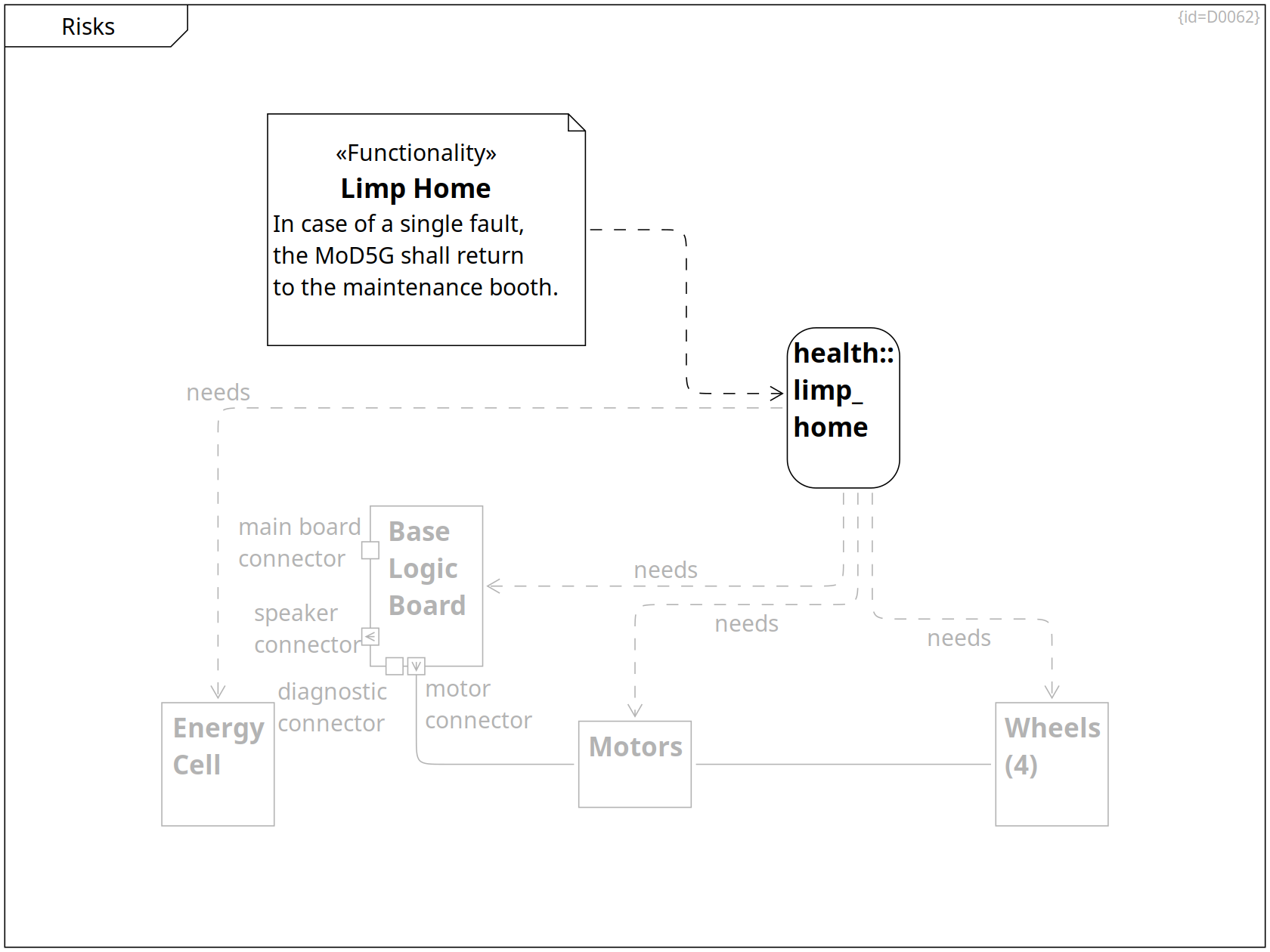
Failure Modes of Energy Cell, Failure Modes of Base Logic Board, Health States, Risks, Failure Modes of Motors and Wheels
health::limp_home State C0032
The MoD5G is not fully healthy anymore,
some of the own HW parts may not work as expected.
In this case where the full operation is not possible anymore, the MoD5G shall drive back to the home charging station.
needs ··> Energy Cell Dependency R0333
needs ··> Base Logic Board Dependency R0334
needs ··> Motors Dependency R0335
needs ··> Wheels (4) Dependency R0336
Risks
Limp Home Functionality Comment C0206
In case of a single fault,
the MoD5G shall return
to the maintenance booth.
··> health::limp_home Dependency R0331
Failure Modes of Energy Cell, Mechanics, Risks, Power Distribution
Energy Cell Block C0046
An energy cell provides power sufficient for a 1-day mission.
Mechanics, Risks, Failure Modes of Motors and Wheels, Electric Parts and Electronics
Motors Block C0040
There are two motors to drive and steer and further motors to control the movement of a tool-arm.
-- Wheels (4) Communication Path R0332
Mechanics, Risks, Failure Modes of Motors and Wheels
Wheels (4) Block C0038
The functionality of wheels is to transform a torque force into movement of the MoD5G.
Base Logic Board, Requirements, Failure Modes of Base Logic Board, Inner World, Solution Strategy, Physical View, Risks, Electric Parts and Electronics, Power Distribution
Base Logic Board Block C0048
The base logic board consists of several electronic parts shown in Base Logic Board.
It provides functionality to detect health status of MoD5G components, it steers motors.
main board connector Port F0031
speaker connector Output Port F0049
diagnostic connector Port F0051
motor connector Output Port F0050
-- Motors Communication Path R0326
Failure Modes of Energy Cell
Failure Modes of Energy Cell Use Case Diagram D0063
This section lists the failure modes of the energy cell and their effects.
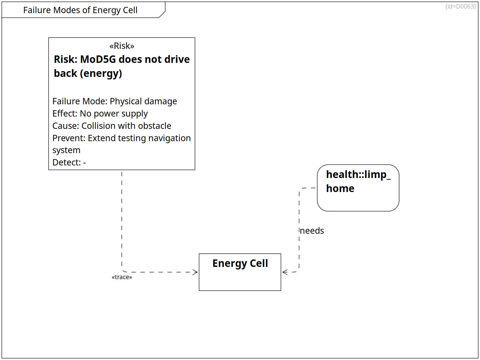
Failure Modes of Energy Cell, Failure Modes of Base Logic Board, Health States, Risks, Failure Modes of Motors and Wheels
health::limp_home State C0032
The MoD5G is not fully healthy anymore,
some of the own HW parts may not work as expected.
In this case where the full operation is not possible anymore, the MoD5G shall drive back to the home charging station.
needs ··> Energy Cell Dependency R0333
Failure Modes of Energy Cell, Mechanics, Risks, Power Distribution
Energy Cell Block C0046
An energy cell provides power sufficient for a 1-day mission.
Failure Modes of Energy Cell
Risk: MoD5G does not drive back (energy) Risk Requirement C0147
- cause/fault: the energy cell is damaged
- risk/failure: the MoD5G cannot drive anymore
Failure Mode: Physical damage Tagged Value F0063
Effect: No power supply Tagged Value F0064
Cause: Collision with obstacle Tagged Value F0047
Prevent: Extend testing navigation system Tagged Value F0065
Detect: - Tagged Value F0066
··> Energy Cell Trace R0339
Failure Modes of Base Logic Board
Failure Modes of Base Logic Board Use Case Diagram D0064
This section lists the failure modes of the base logic board and their effects.
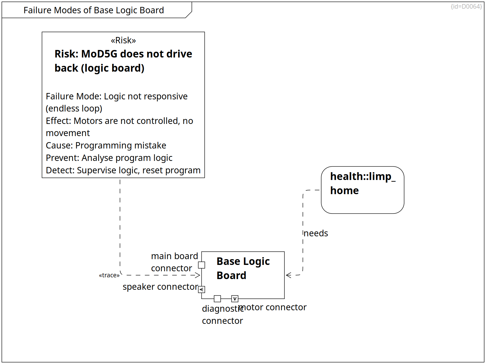
Failure Modes of Energy Cell, Failure Modes of Base Logic Board, Health States, Risks, Failure Modes of Motors and Wheels
health::limp_home State C0032
The MoD5G is not fully healthy anymore,
some of the own HW parts may not work as expected.
In this case where the full operation is not possible anymore, the MoD5G shall drive back to the home charging station.
needs ··> Base Logic Board Dependency R0334
Base Logic Board, Requirements, Failure Modes of Base Logic Board, Inner World, Solution Strategy, Physical View, Risks, Electric Parts and Electronics, Power Distribution
Base Logic Board Block C0048
The base logic board consists of several electronic parts shown in Base Logic Board.
It provides functionality to detect health status of MoD5G components, it steers motors.
main board connector Port F0031
speaker connector Output Port F0049
diagnostic connector Port F0051
motor connector Output Port F0050
Failure Modes of Base Logic Board
Risk: MoD5G does not drive back (logic board) Risk Requirement C0133
- cause/fault: the base logic board is damaged
- risk/failure: the MoD5G cannot drive anymore
Failure Mode: Logic not responsive (endless loop) Tagged Value F0059
Effect: Motors are not controlled, no movement Tagged Value F0060
Cause: Programming mistake Tagged Value F0048
Prevent: Analyse program logic Tagged Value F0061
Detect: Supervise logic, reset program Tagged Value F0062
··> Base Logic Board Trace R0338
Failure Modes of Motors and Wheels
Failure Modes of Motors and Wheels Use Case Diagram D0012
This section lists the failure modes of motors and wheels and their effects.
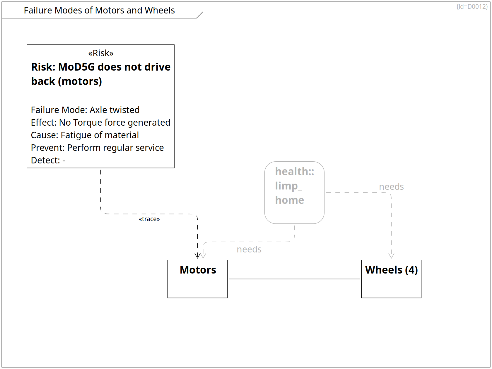
Failure Modes of Energy Cell, Failure Modes of Base Logic Board, Health States, Risks, Failure Modes of Motors and Wheels
health::limp_home State C0032
The MoD5G is not fully healthy anymore,
some of the own HW parts may not work as expected.
In this case where the full operation is not possible anymore, the MoD5G shall drive back to the home charging station.
needs ··> Motors Dependency R0335
needs ··> Wheels (4) Dependency R0336
Failure Modes of Motors and Wheels
Risk: MoD5G does not drive back (motors) Risk Requirement C0148
- cause/fault: the ,ovement/steering motors are damaged
- risk/failure: the MoD5G cannot drive anymore
Failure Mode: Axle twisted Tagged Value F0055
Effect: No Torque force generated Tagged Value F0056
Cause: Fatigue of material Tagged Value F0046
Prevent: Perform regular service Tagged Value F0057
Detect: - Tagged Value F0058
··> Motors Trace R0337
Mechanics, Risks, Failure Modes of Motors and Wheels, Electric Parts and Electronics
Motors Block C0040
There are two motors to drive and steer and further motors to control the movement of a tool-arm.
-- Wheels (4) Communication Path R0332
Mechanics, Risks, Failure Modes of Motors and Wheels
Wheels (4) Block C0038
The functionality of wheels is to transform a torque force into movement of the MoD5G.
Glossary
Glossary List D0013
This section explains the used terms. (Domain and Solution Space, System Level)
See also Glossary for software terms.
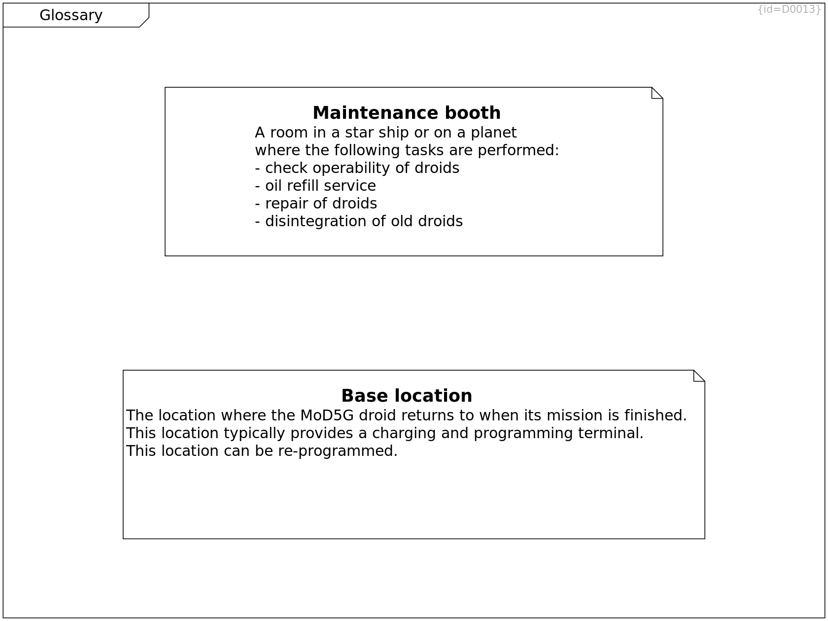
Glossary
Maintenance booth Comment C0104
A room in a star ship or on a planet
where the following tasks are performed:
- check operability of droids
- oil refill service
- repair of droids
- disintegration of old droids
Glossary
Base location Comment C0143
The location where the MoD5G droid returns to when its mission is finished.
This location typically provides a charging and programming terminal.
This location can be re-programmed.
Stereotypes on "What to build"
Stereotypes on "What to build" Profile Diagram D0049
Stereotypes allow a classification of elements into project-specific categories.
This diagram defines stereotypes and their images with focus on the problem space.
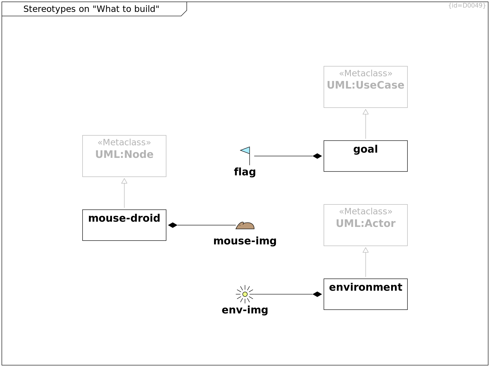
Stereotypes on "What to build"
UML:Node Metaclass Stereotype C0165
Stereotypes on "What to build"
mouse-droid Stereotype C0163
<path
d="
c 3, -0.8 4.5, 0.5 4.5, 2.5
l -8, 0
c 1, -2, 2, -3, 3, -3
c 0.5, 0 0.5, 1 0, 1
m -1.1, 0.3
l -0.2, 0.2
"
fill="#bb9977"
/>
*-- mouse-img Composition R0271
--|> UML:Node Generalization R0272
Stereotypes on "What to build"
mouse-img mouse-droid Image C0164
Stereotypes on "What to build"
UML:UseCase Metaclass Class C0170
Stereotypes on "What to build"
goal Stereotype C0171
<path fill="#aaeeff" d="
M 5,9
L 5,1 1,2.5 5,4
"/>
--|> UML:UseCase Generalization R0277
*-- flag Composition R0278
Stereotypes on "What to build"
flag goal Image C0172
Stereotypes on "What to build"
UML:Actor Metaclass Class C0174
Stereotypes on "What to build"
environment Stereotype C0175
<path fill="#eeff88" d="
M 1,0
C 1,0.55 0.55,1 0,1
C -0.55,1 -1,0.55, -1,0
C -1,-0.55 -0.55,-1 0,-1
C 0.55,-1, 1,-0.55, 1,0
"/>
<path d="
M 2,0 L 4,0
M 1.73,1 L 3.46,2
M 1,1.72 L 2,3.46
M 0,2 L 0,4
M -1,1.72 L -2,3.46
M -1.73,1 L -3.46,2
M -2,0 L -4,0
M -1.73,-1 L -3.46,-2
M -1,-1.72 L -2,-3.46
M 0,-2 L 0,-4
M 1,-1.72 L 2,-3.46
M 1.73,-1 L 3.46,-2
"/>
--|> UML:Actor Generalization R0281
*-- env-img Composition R0282
Stereotypes on "What to build"
env-img environment Image C0176
Stereotypes on "How to achieve the goal"
Stereotypes on "How to achieve the goal" Profile Diagram D0048
Stereotypes allow a classification of elements into project-specific categories.
This diagram defines stereotypes and their images with focus on the solution space.
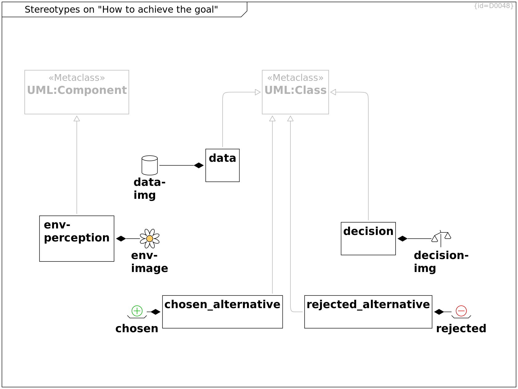
Stereotypes on "How to achieve the goal"
UML:Component Metaclass Class C0155
Stereotypes on "How to achieve the goal"
env-perception Stereotype C0156
<path
fill="#ffcc66"
d="
M 0.8,0
a 0.8,0.8 0 1 0 -1.6,0
a 0.8,0.8 0 1 0 1.6,0
"
/>
<path
d="
M 1,0
A 1,0.5 22 1 1 0.707,0.707
A 1,0.5 67 1 1 0,1
A 1,0.5 112 1 1 -0.707,0.707
A 1,0.5 157 1 1 -1,0
A 1,0.5 202 1 1 -0.707,-0.707
A 1,0.5 247 1 1 0,-1
A 1,0.5 -68 1 1 0.707,-0.707
A 1,0.5 -23 1 1 1,0
"
/>
--|> UML:Component Generalization R0265
*-- env-image Composition R0266
Stereotypes on "How to achieve the goal"
env-image env-perception Image C0157
The symbol of a flower was chosen to depict sensors for the environment: the flower is found by insects by visual and chemical sensors.
Stereotypes on "How to achieve the goal"
UML:Class Metaclass Class C0158
Stereotypes on "How to achieve the goal"
decision Stereotype C0159
<path d="m 8,12 l -4,7 1,1 6,0 1,-1 -4,-7 l 8,-4 9,0 l -4,7 1,1 6,0 1,-1 -4,-7 " /><path d="m 15,5 l 1,3 m 0,2 l 0,17 " />
--|> UML:Class Generalization R0267
*-- decision-img Composition R0268
Stereotypes on "How to achieve the goal"
decision-img decision Image C0160
Stereotypes on "How to achieve the goal"
data Stereotype C0161
<path d="m 4,5 l 0,22 c 0,2.25 5.25,4 12,4 s 12,-1.75 12,-4 l 0,-22 " /><path d="m 4,5 c 0,-2.25 5.25,-4 12,-4 s 12,1.75
12,4 s -5.25,4 -12,4 s -12,-1.75 -12,-4 " />
--|> UML:Class Generalization R0269
*-- data-img Composition R0270
Stereotypes on "How to achieve the goal"
data-img data Image C0162
Stereotypes on "How to achieve the goal"
rejected_alternative Stereotype C0166
<path d="m 1,24 4,4 22,0 4,-4 " /><path stroke="#cc0000" d="m 8,17 c 0,-4.4 3.6,-8 8,-8 s 8,3.6 8,8 s -3.6,8 -8,8 s
-8,-3.6 -8,-8 " /><path stroke="#cc0000" d="m 11,17 l 10,0 " />
*-- rejected Composition R0273
--|> UML:Class Generalization R0274
Stereotypes on "How to achieve the goal"
rejected rejected_alternative Image C0167
Stereotypes on "How to achieve the goal"
chosen_alternative Stereotype C0168
<path d="m 1,24 4,4 22,0 4,-4 " /><path stroke="#00aa00" d="m 8,17 c 0,-4.4 3.6,-8 8,-8 s 8,3.6 8,8 s -3.6,8 -8,8 s
-8,-3.6 -8,-8 " /><path stroke="#00aa00" d="m 11,17 l 10,0 m -5,-5 l 0,10 " />
*-- chosen Composition R0275
--|> UML:Class Generalization R0276
Stereotypes on "How to achieve the goal"
chosen chosen_alternative Image C0169
Stereotypes on "How to achieve the goal"
SW Stereotype C0196
<path fill="#eeffdd" d="
M 0,-1
M 1.5,5
L 2,3
C 4,2 6,2, 8,3
L 8.5,5 7.5,5 8,4
C 6,5 4,5 2,4
L 2.5,5 1.5,5
" />
*-- SW-img Composition R0306
--|> SysML:block Generalization R0346
Stereotypes on "How to achieve the goal"
SW-img SW Image C0197
Stereotypes on "How to achieve the goal"
HW Stereotype C0198
<path fill="#eeddff" d="
M 1,3
L 5,1 7,1 7.5,2 2,5 z
" />
<path d="
M 4,4
L 7,10 8,9.5 5,3.5
" />
*-- HW-img Composition R0307
--|> SysML:block Generalization R0345
Stereotypes on "How to achieve the goal"
HW-img HW Image C0199
Stereotypes on "How to achieve the goal"
EE Stereotype C0200
<path fill="#ffffdd" d="
M 1,5
L 3,5 3,3.5, 5,5 3,6.5 3,5
M 5,3.5
L 5,6.5
M 5,5
L 7,5" />
<path d="
M 4,3
L 5,1 4.5,1.5
M 5,3
L 6,1 5.5,1.5
" />
*-- EE-img Composition R0308
--|> SysML:block Generalization R0344
Stereotypes on "How to achieve the goal"
EE-img EE Image C0201
Stereotypes on "How to achieve the goal"
locigal_form Stereotype C0207
<path d="
M 0,5.5
c 0,0.5 1,0.5 3,0.5
L 4,8
5.5,8
5,6
c 2,0 2,-0.5 3.5,-1
L 9,4
8,4
7.5,5
5.25,5
5.5,4
4,4
3,5
c -1,0 -3,0 -3,0.5
">
</path>
*-- Logical-img Composition R0342
--|> SysML:block Generalization R0343
Stereotypes on "How to achieve the goal"
Logical-img locigal_form Image C0208
The symbol of an airplane was chosen to depict that form follows function: the shape of the airplane is derived from the fly-function.
Stereotypes on "How to achieve the goal"
SysML:block Metaclass Stereotype C0209